Lacing device

Inactive Publication Date: 2007-08-09
APLER MAGNUS
View PDF11 Cites 9 Cited by
  • Summary
  • Abstract
  • Description
  • Claims
  • Application Information

AI Technical Summary

Benefits of technology

[0007] The lacing device provided according to the invention is extremely advantageous since it is safely and tightly mo

Problems solved by technology

If the button should be exposed to great strain, such as jerks, impacts or great tensile stress, there is an eminent risk that the button would come loose from the fabric to which it is fastened.
This prior-art fastening device for waterproof shoes has the drawback that, after fastening to the upper leather, it constitutes a fixed portion of the shoe.
For instance, for a sports shoe or casua

Method used


Image

  • Lacing device
  • Lacing device
  • Lacing device

Examples


Embodiment Construction

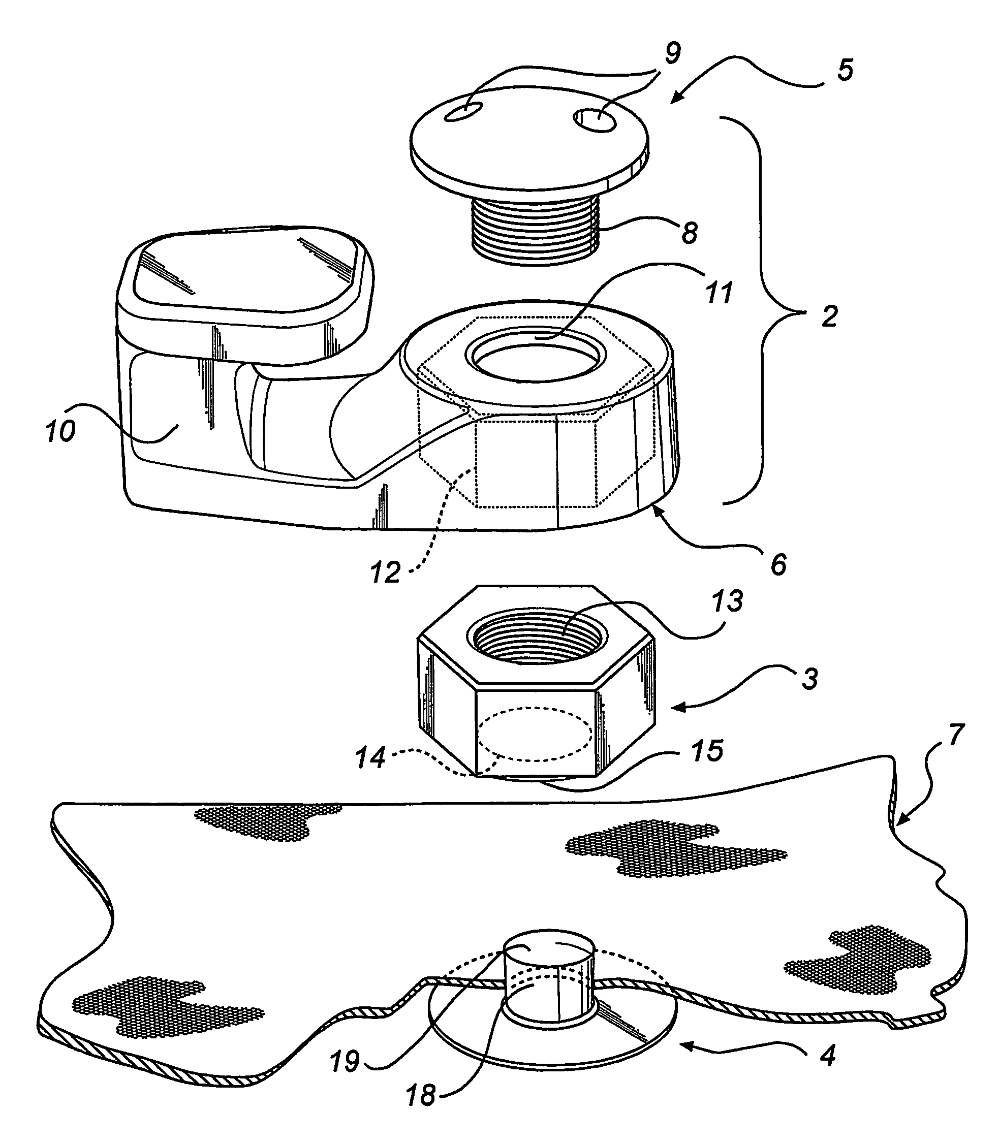
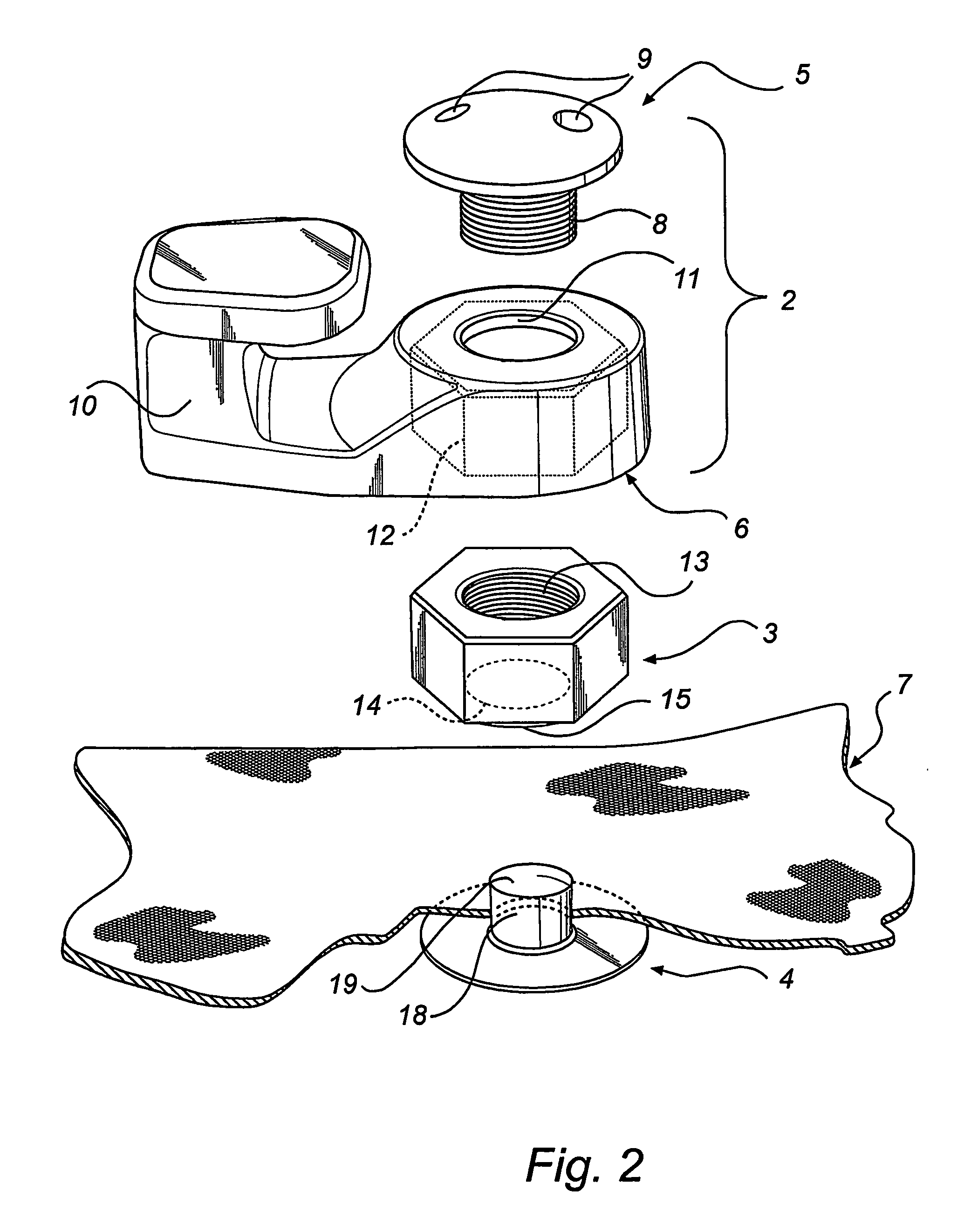
[0014]FIGS. 2-3 illustrate a lacing device 1 according to an embodiment of the invention, which comprises a lace holding part 2, an intermediate fastening element 3 and an inner fastening element 4. The lace holding part 2 in turn comprises an outer fastening element 5 and a lace-catching element in the form of a lace hook 6. The drawings also show a flexible piece of material 7, to which the lacing device 1 is adapted to be attached.

[0015] The outer fastening element 5 in the lace holding part 2 is provided with external threads 8 and, for the purpose of being tightened and loosened, also at least one recess 9 for a screw tool. The lace hook 6 in the lace holding part 2 has a hook part 10, a fastening hole 11 for fastening the outer fastening element 5 from the outside, and a depression 12 which is formed to enclose and position to the hook part 10 of the lace hook 6. Positioning can take place by means of supplementary non-round or regularly polygonal shapes of the depression 12 ...


PUM


Abstract

A lacing device is disclosed for fastening to a flexible piece of material. Further, a method of mounting a lacing device is also disclosed. The lacing device has a lace holding part, an intermediate fastening element and an inner fastening element. The inner fastening element is adapted to make, in the mounted state, permanent engagement with the intermediate fastening element. The lace holding part is detachable.

Description

FIELD OF THE INVENTION [0001] The invention relates to a lacing device comprising at least one lace holding part, an inner fastening element and an intermediate fastening element for fastening to a flexible piece of material, said piece of material being located between said inner fastening element and said intermediate fastening element. BACKGROUND ART [0002] An example of a traditionally designed device of the type described by way of introduction is disclosed in U.S. Pat. No. 1,594,416, which describes a button with an internal thread that is screwed on the externally threaded pin of a “link part”. The pin of the “link part” is hollow and also internally threaded, so that the underside of the “link part” can be made to abut against a fabric and be screwed to a plate provided with a pointed, threaded stud and located on the inside of the fabric. In fastening, the pointed stud of the plate is pressed through the fabric, after which the “link part” is threaded onto the stud and the ...

Claims


Application Information

Patent Timeline
IPC IPC(8): A43C3/00
CPCY10T24/375A43C3/00
Inventor APLER, MAGNUS
Owner APLER MAGNUS
Why Eureka
Try Eureka