Scribe head and scribe device

a scribe and scribe technology, applied in the field of scribe head and scribe device, can solve problems such as difficulty in maintaining the constant cutting edge load

Inactive Publication Date: 2007-08-09
MITSUBOSHI DIAMOND IND CO LTD
View PDF8 Cites 20 Cited by
  • Summary
  • Abstract
  • Description
  • Claims
  • Application Information

AI Technical Summary

Benefits of technology

[0033] The motive power transmission means can effectively convert the change of force, received from the scribing line forming means, into a rotational direction and transmit it to the rotation means. Furthermore, the motive power transmission means can effectively convert the change of force, received from the rotation means, into a linear direction and transmit it to the scribing line forming means. As a result, the scribing line forming means can be effectively press against the substrate with a constant magnitude.
[0034] The motive power transmission means may include a face which is tilted by approximately 45 degrees with respect to

Problems solved by technology

Therefore, it is difficult to maintain the cutting edge load

Method used


Image

  • Scribe head and scribe device
  • Scribe head and scribe device
  • Scribe head and scribe device

Examples


Embodiment Construction

[0066] Hereinafter, Embodiments of the present invention will be described with reference to the accompanying drawings.

[0067] 1. Scribing Apparatus

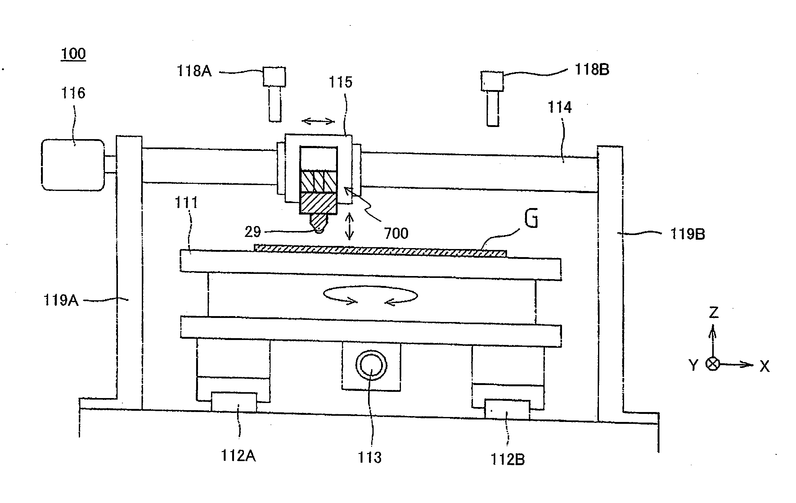
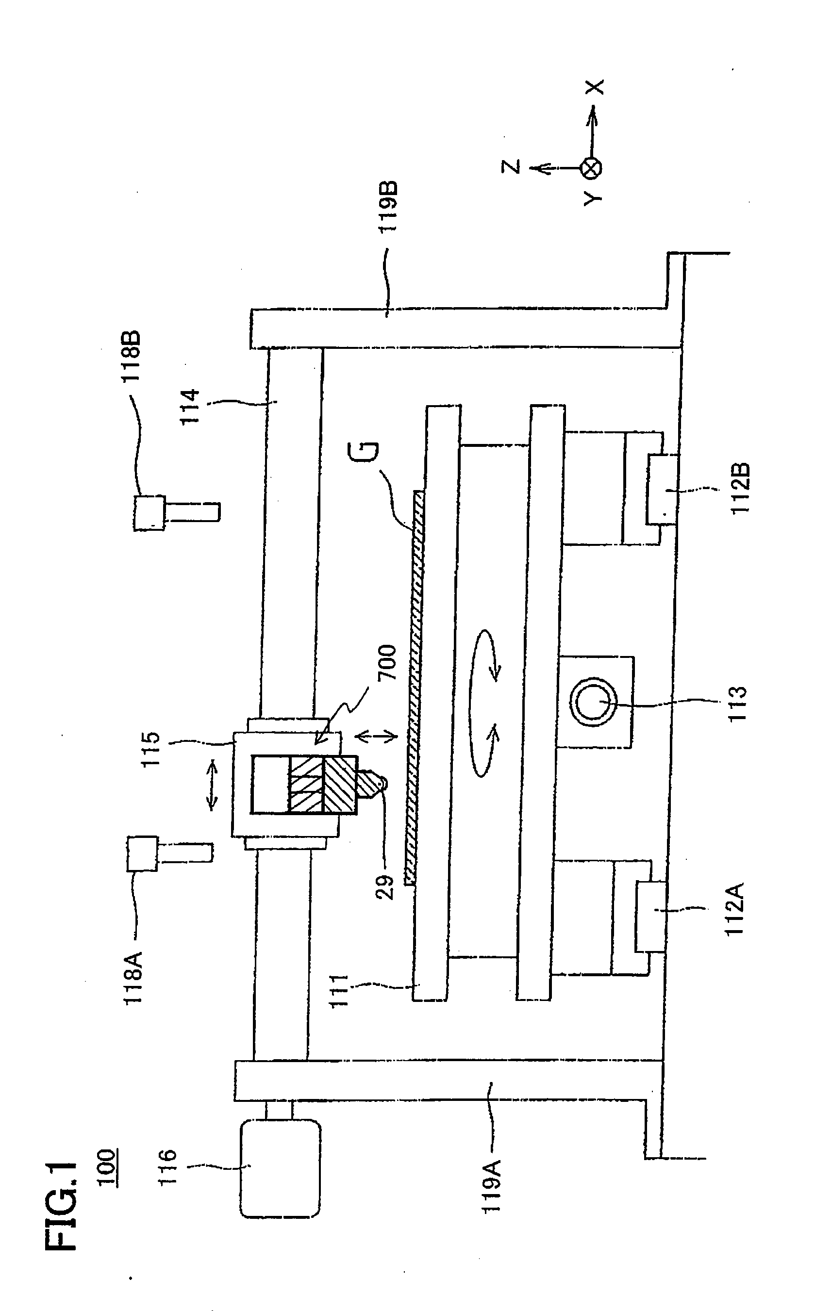
[0068]FIG. 1 shows an example of a structure of a scribing apparatus 100 according to an Embodiment of the present invention. The scribing apparatus 100 includes a table 111, a first guide rail 112A, a second guide rail 112B and a ball screw 113.

[0069] The table 111 is structured so as to be rotatable in a horizontal plane. A vacuum adsorption means (not shown) is provided in the table 111. The vacuum adsorption means fixes a substrate G (e.g., brittle substrate including a glass plate) mounted on the table 111 to the table 111. The first guide rail 112A and the second guide rail 112B support the table 111 such that the table 111 is movable in the Y-direction. The first guide rail 112A and the second guide rail 112B are provided in parallel to each other. The ball screw 113 moves the table111 along the first guide rail 112A and the sec...


PUM

PropertyMeasurementUnit
Angleaaaaaaaaaa
Poweraaaaaaaaaa
Efficiencyaaaaaaaaaa

Abstract

A scribing head according to the present invention includes: a scribing line forming means (29) structured so as to form a scribing line on a substrate; and a moving means (502, 503) for moving the scribing line forming means such that the scribing line forming means presses the substrate with a constant magnitude, wherein the moving means includes: a rotation means (502) rotating about a rotation axis, the axial center of the rotation axis being provided so as to align with a predetermined direction in which the scribing line forming means moves, and a motive power transmission means (503) for transmitting a motive power between the motive power transmission means and the scribing line forming means such that the scribing line forming means moves on a straight line along the axial center of the rotation axis in response to the rotation of the rotation means, the motive power transmission means being provided along the predetermined direction.

Description

TECHNICAL FIELD [0001] The present invention relates to a scribing head used to form a scribing line on a substrate and a scribing apparatus including the scribing head. BACKGROUND ART [0002] For example, when a glass substrate (including a brittle material) is cut into a desired size, a cutting edge of a cutter wheel is pressed onto a surface of the brittle material with a predetermined force and is moved on the surface of the glass substrate. As a result, a scribing line is formed (hereinafter, referred to as a “scribing step”). Thereafter, a predetermined force is applied to the glass substrate along the scribing line (hereinafter, referred to as a “breaking step”). As a result, the glass substrate is cut along the scribing line. [0003]FIG. 7 shows an example of a structure of a conventional scribing apparatus 10. The scribing apparatus 10 performs the scribing step. [0004] The scribing apparatus 10 includes a table 11, a first guide rail 12A, a second guide rail 12B and a ball s...

Claims


Application Information

Patent Timeline
IPC IPC(8): B43L13/00B28D1/22C03B33/027C03B33/10
CPCB28D1/225C03B33/107C03B33/10C03B33/027Y10T83/0333Y10T83/0393Y10T225/30Y10T225/325Y10T225/371Y02P40/57C03B33/033
Inventor NISHIO, YOSHITAKA
Owner MITSUBOSHI DIAMOND IND CO LTD
Why Eureka
Try Eureka