
Systems for cost effective concentration and utilization of solar energy

a technology of solar energy and concentrated photovoltaics, applied in the direction of pv power plants, indirect heat exchangers, lighting and heating apparatus, etc., can solve the problems of limiting reducing the efficiency of the manufacturing process, and reducing the production capacity of a given investment in tooling. , to achieve the effect of low iron content, low absorption and low dispersion

Inactive Publication Date: 2012-02-16
NORMAN RICHARD
View PDF2 Cites 53 Cited by
  • Summary
  • Abstract
  • Description
  • Claims
  • Application Information

AI Technical Summary

Benefits of technology

[0015]It is an even further object of the present invention to accomplish this with a mirror shape that is symmetrical so that it can be shaped by shaping means, on each side of the mirror's frame, that are identical, and so that during installation it does not matter which end of the mirror is placed in which direction, reducing installation errors.
[0212]“Triple junction Cell” as used herein means a photovoltaic cell that has three different junctions with three different band-gaps stacked on one another so that each can absorb photons of an energy that it can convert efficiently to electricity. Triple junction cells currently have a maximum efficiency of around 40%, which is much higher than that of silicon cells or thin film photovoltaics. On the other hand, triple junction cells currently cost 200 times more per area than silicon cells, and so require concentrated light to be economical.

Problems solved by technology

However these methods require extensive time on an expensive mandrel, which limits production capacity from a given investment in tooling.
But such precision adds cost to the manufacturing process.
However fabricating these numerous narrow and deep channels by etching a block of silicon or machining a block of copper with saws or with electron discharge machining is expensive and time consuming.
When cells are widely separated this adds only a small cost from needing slightly larger cells to cover for this inaccuracy, but in dense arrays the 50-micron gap remains unfilled, reducing efficiency.
However there is no room for such a separate wire in a dense receiver array.
However the bus bar covers a few percent of the cell surface, and while the bus bar is in turn covered by active cell area on the next cell, the bus bar still increases the size of the cell and thus reduces the number of cells per wafer and raises the cell cost.
Shingling the cells also slants the cells relative to the incoming light, increasing the incidence angle for light from one side and decreasing it for the other side, creating asymmetry in the optics that complicates obtaining an even focus.
While this allows even passive cooling to keep the cells below their maximum operating temperature, it require extensive inter-cell wiring and a sealed unit the size of the whole system's aperture.
Systems that use a multi-cell focus use dense arrays that conveniently centralize the electronics (Lasich '456), but such arrays are hard to cool well even with pumped-liquid active cooling and require expensive mini-channel or micro-channel coolers.
However high-concentration photovoltaic system only work when pointed accurately at the sun so implementing this anti-shading algorithm with high concentration photovoltaic systems would generally misalign all systems enough that no appreciable power would be generated.

Method used


Image

  • Systems for cost effective concentration and utilization of solar energy
  • Systems for cost effective concentration and utilization of solar energy
  • Systems for cost effective concentration and utilization of solar energy

Examples


Embodiment Construction

First Family of Preferred Embodiments

Improvements to Methods for Making Pre-Shaped Reflective Panels for High-Concentration Solar Systems

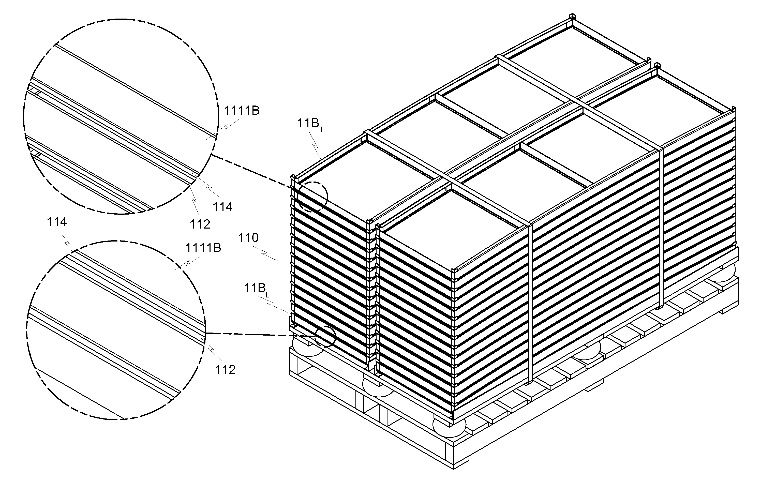
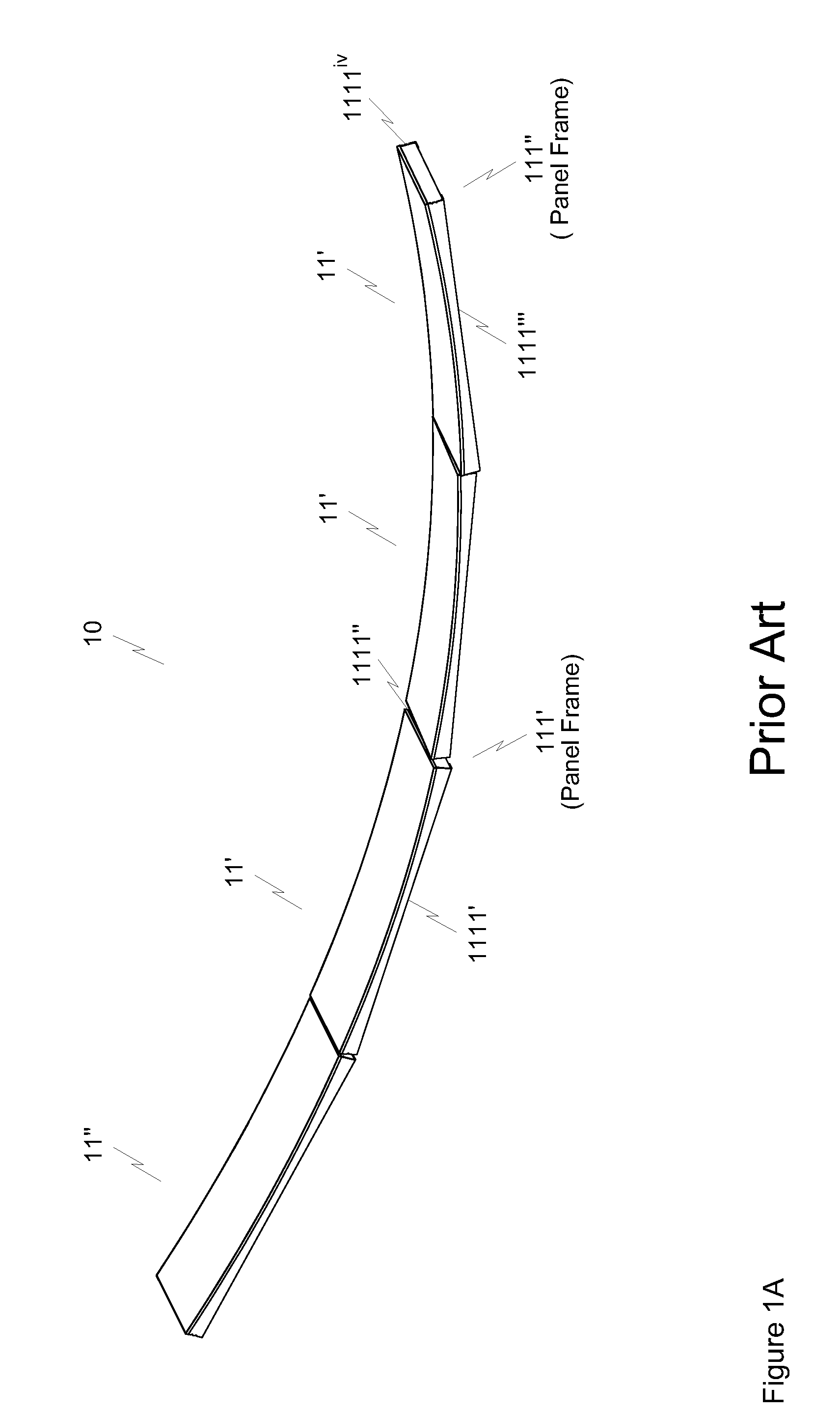
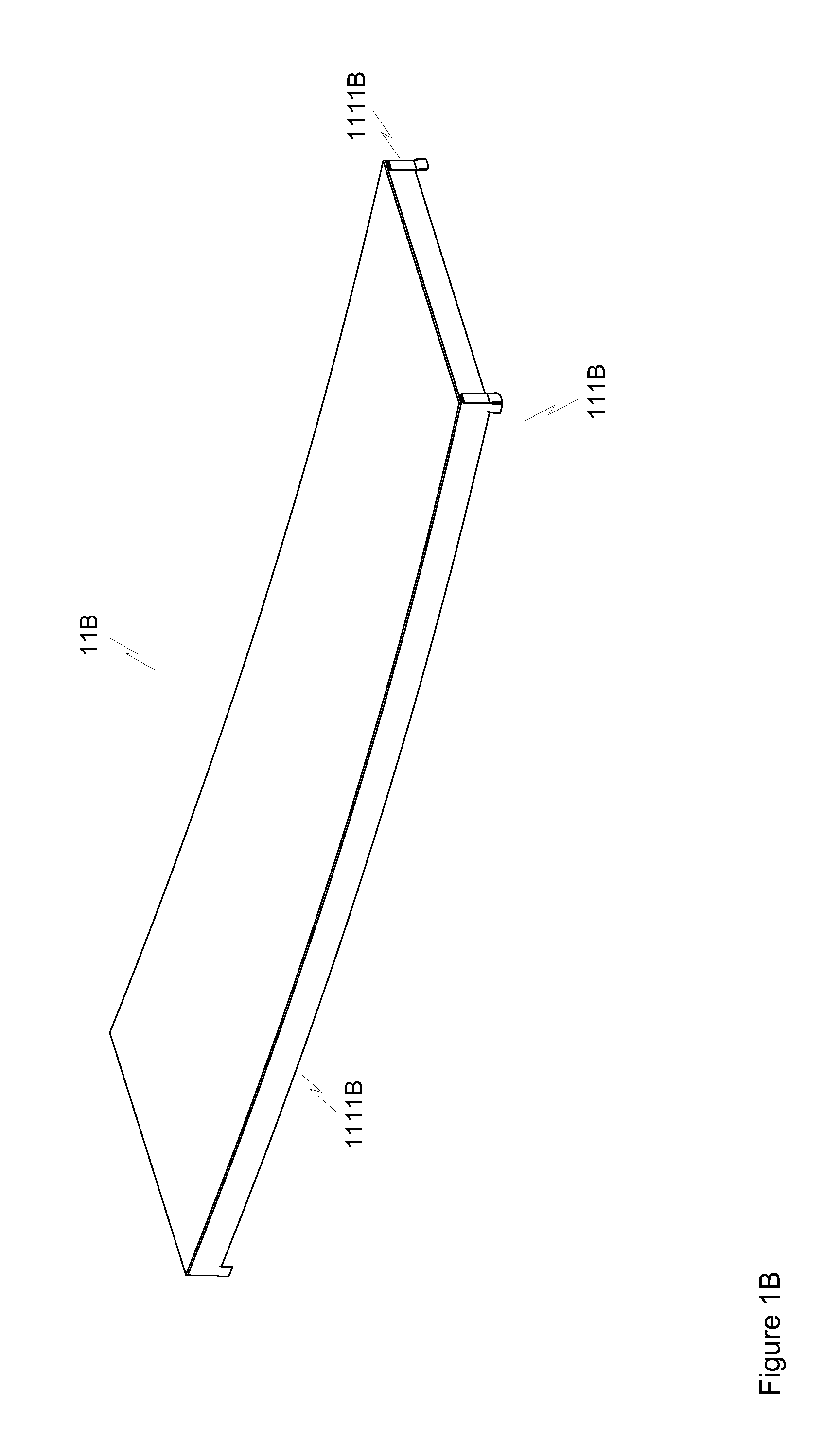
[0429]Pre-shaped solar glass mirrors offer the highest specular reflectivity of any current cost-effective reflective surface, and also offer one of the most scratch-resistant surfaces and have the longest proven field life as well. However pre-shaped solar glass mirrors are currently too expensive. Pre-shaped glass parabolic trough segments are generally made by pressing flat mirrored glass sheets against an accurately curved parabolic mandrel while an adhesive bonding the glass to a sturdy backing material sets, or similarly pre-shaping a backing material and then bonding the glass to it (“Sandwich Construction Solar Structural Facets, Sandia National Labs 1999), or by slump-molding glass against an accurate mandrel. When the glass is thin enough and the curvature is slight enough, even compound curves can be formed in glass mirrors by cold press...


PUM


Abstract

The present invention is primarily directed to improvements to cost-effective systems for concentrating and using solar energy. The present invention co-optimizes the frame and the primary mirrors and secondary concentrator for a cost-effective very high concentration quasi-parabolic dish system that uses no moulded optics for the primary concentration, and also optimizes fabrication jigs for the main components of that design. The present invention also optimizes cell contacts and provides cost effective receiver cooling for dense receiver arrays for very high concentration photovoltaic systems. The present invention also includes a semi-dense receiver array that can provide a higher acceptance angle than a dense receiver array, and finally includes mutual-shading impact minimization methods and apparatus compatible with very high concentration photovoltaic systems.

Description

TECHNICAL FIELD[0001]This invention relates to the field of solar mirror fabrication and alignment, concentrated photo-voltaics, photo-voltaic receivers, heat exchangers and control systems for photo-voltaic systems.SUMMARY OF THE PRIOR ART[0002]Pre-shaped glass mirrors offer the highest specular reflectivity, and pre-shaped glass parabolic trough segments are generally made by pressing mirrored glass against an accurately curved parabolic mandrel while an adhesive bonding the glass to a sturdy backing material sets, locking in the appropriate curvature (“Sandwich Construction Solar Structural Facets”, Sandia National Laboratories; and “Further Analysis of Accelerated Exposure Testing of Thin-Glass Mirror”, Kennedy et al, ES2007), or similarly pre-shaping a backing material and then bonding the glass to it using a mandrel (U.S. Pat. No. 7,550,054, Lasich), or slump-molding glass against an accurate mandrel. However these methods require extensive time on an expensive mandrel, which ...

Claims


Application Information

Patent Timeline
Patent Type & Authority Applications(United States)
IPC IPC(8): H01L31/052F24S23/71F24S50/20
CPCY02E10/52Y02E10/42F28D15/0233H01L31/02H02S20/00H01L31/056H01L31/18H02S40/425F24S23/71F24S30/452F24S2023/876H01L31/022425H01L31/0508H01L31/0547F24S23/74Y02E10/40
Inventor NORMAN, RICHARDST. CROIX, FREDERICK DE
Owner NORMAN RICHARD
Learn More