Recharging system for electrically powered vehicle, and vehicle incorporating same

a charging system and electric power technology, applied in the direction of energy harvesting concepts, machines/engines, rider propulsion, etc., can solve the problems of incompatible with desirable vehicular aesthetics, inability to efficiently convert air flow forces into electric energy, and inability to meet the requirements of vehicle performance, etc., to achieve efficient conversion of the thrust of moving air

Inactive Publication Date: 2010-02-23
WALSH RICHARD T
View PDF59 Cites 59 Cited by
  • Summary
  • Abstract
  • Description
  • Claims
  • Application Information

AI Technical Summary

Benefits of technology

[0003]Broad objects of the present invention are to provide a novel system for efficiently converting the thrust of moving air into electric energy for recharging on-board batteries of an electrically powered motor vehicle into which the system is integrated; to provide a novel electrically powered motor vehicle having an integral battery recharging system; and to provide a novel method for effecting recharging of the batteries of an electric vehicle.
[0004]Additional objects of the invention are to provide such a recharging system and method which can be integrated and implemented, respectively, in an electrically powered motor vehicle without substantially diminishing the performance and aesthetic character of the vehicle, and to provide an attractive and high-performing electrically powered motor vehicle having integrated therein the battery-recharging capability afforded by such a system and method.
[0008]Still other objects of the invention are attained by the provision of a method for effecting recharging of rechargeable battery means carried on-board an electrically powered motor vehicle, wherein the vehicle and the integral recharging system are constructed in accordance with the present description. Recharging of the battery means is effected by propelling the motor vehicle forwardly so as to cause air to flow through the conduit, from the entrance end toward the exit end thereof, and also to cause air to pass along the underside of the motor vehicle to thereby promote air flow through the conduit toward the exit end. The flowing air causes the rotor structures of the electric generators to rotate, to in turn generate electric current and thus effect recharging of the operatively connected battery means.

Problems solved by technology

Despite the activity in the art indicated by the foregoing, in many instances the recharging systems heretofore provided do not function efficiently to convert air flow forces into electric energy.
Moreover, the prior art systems would often diminish the performance of the vehicle, and they tend to be unsightly or, at best, to be incompatible with desirable vehicular aesthetics.

Method used


Image

  • Recharging system for electrically powered vehicle, and vehicle incorporating same
  • Recharging system for electrically powered vehicle, and vehicle incorporating same

Examples


Embodiment Construction

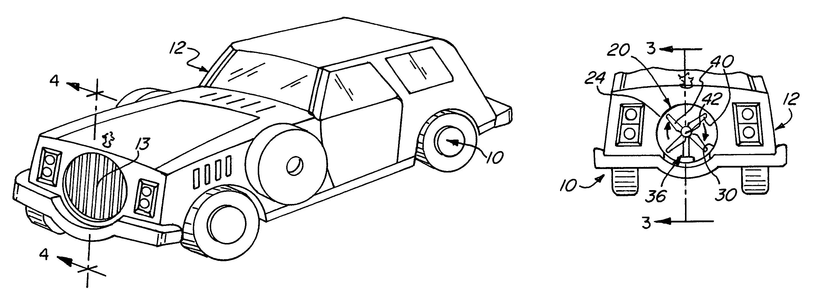
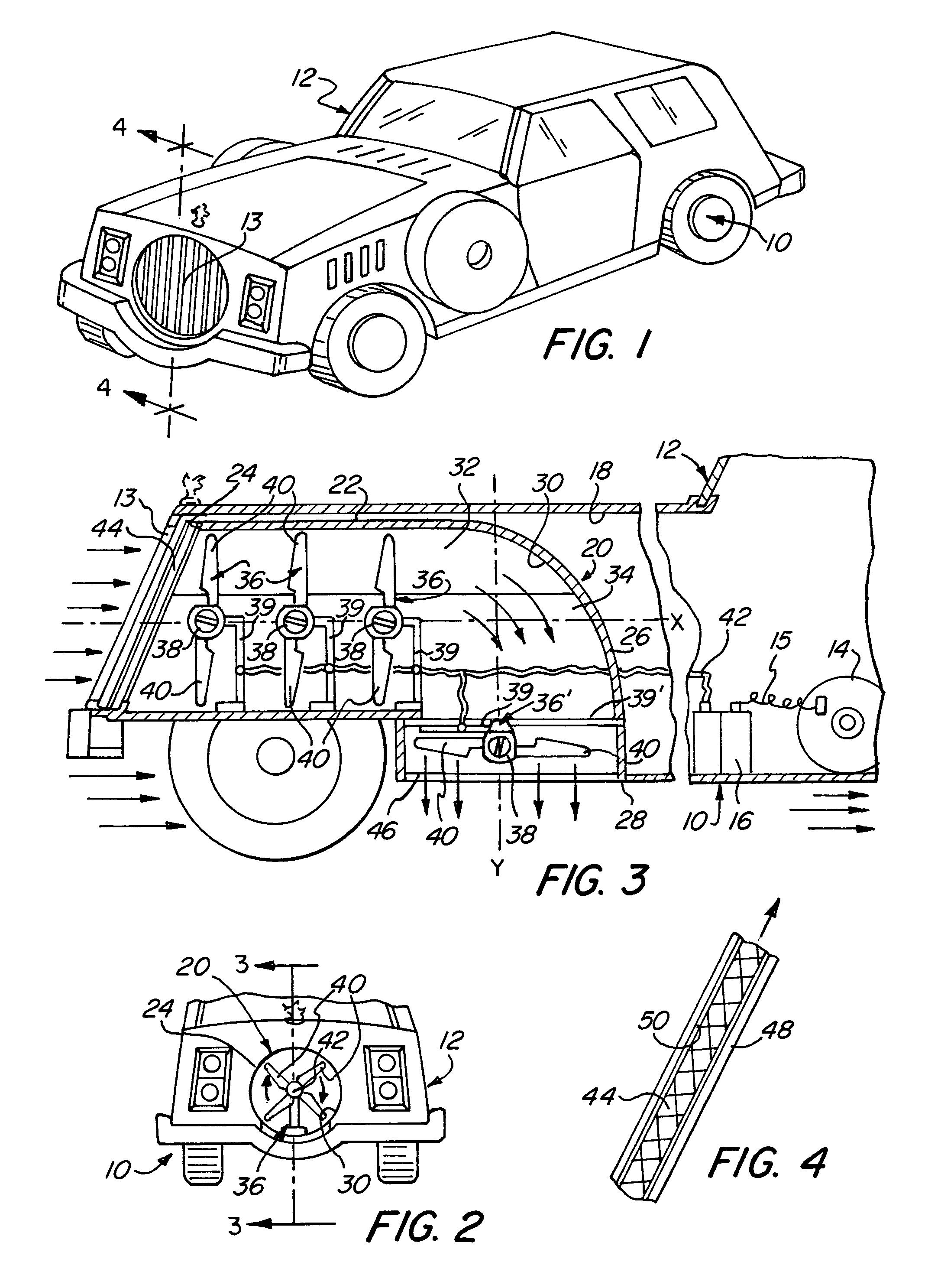
[0013]Except for modifications made to accommodate the battery recharging system of the invention, the automobile depicted in FIG. 1 may be of conventional design and construction. Thus, it is noted, that viewed from the exterior, the automobile shows little or no evidence that it includes a battery recharging system; it is entirely aesthetic, with no external structural or mechanical features or units that would detract from its appearance. The absence of such features and units also avoids the undesirable performance effects that would result from the introduction of air turbulence, wind resistance, increased drag, and the like.

[0014]The automobile comprises, more particularly, a chassis and a body, generally designated respectively by the numerals 10 and 12. A circular grille 13 is affixed at the front end of the body 10, and will desirably be mounted for removal or displacement so as to facilitate access to the recharging system components. As seen in FIG. 3, the automobile also...


PUM


Abstract

An electrically powered motor vehicle includes a system for recharging the on-board batteries, which system includes an air-flow conduit with an entrance at the front of the vehicle, a plurality of electric turbines mounted in tandem within a first portion of the conduit, and an additional electric turbine mounted within a second portion of the conduit, which exits at the underside of the vehicle. The tandem-mounted turbines are disposed for effective rotation, in reaction to air flow, on a generally horizontal axis, and the additional electric turbine is mounted for rotation in reaction to air flow on a second axis, generally transverse to the first axis and disposed proximate the exit end of the conduit.

Description

BACKGROUND OF THE INVENTION[0001]A factor that is primary in the development of a practical electrically powered vehicle concerns the ability to conveniently and efficiently recharge the on-board batteries that serve as the power source. “The charging and recharging of electric vehicle batteries is a critical part of the energy cycle of an electric vehicle.” (The Electric Car, Westbrook, M. H., The Institution of Engineering and Technology, and Society of Automotive Engineers, 2001, 2007) It has long been proposed to incorporate air-driven electric current generators of various kinds into electric vehicles for recharging their batteries, as evidenced by the following U.S. Pat. Nos. Dutchak No. 3,621,930, Stoeckert No. 3,876,925, Sparks No. 4,132,282, Treat No. 4,141,424, Howe No. 4,179,007, Han et al. No. 4,254,843, Boodman et al. No. 4,314,160, and Damron et al. No. 5,920,127.[0002]Despite the activity in the art indicated by the foregoing, in many instances the recharging systems ...

Claims


Application Information

Patent Timeline
Patent Type & Authority Patents(United States)
IPC IPC(8): B60K16/00
CPCB60K16/00B60L8/006F03D9/002B60K2016/006Y02E10/725F05B2240/941Y02T10/7083Y02T10/90F03D9/25Y02E10/728F03D1/04F03D1/02F03D9/32Y02E10/72Y02T10/7072
Inventor WALSH, RICHARD T.
Owner WALSH RICHARD T
Why Eureka
Try Eureka