
High flow air filtration system for ford truck

a high-flow air filtration and ford truck technology, applied in the direction of chemistry apparatus and processes, separation processes, dispersed particle separation, etc., can solve the problems of reducing engine efficiency, horsepower, torque, fuel economy, and other performance parameters, and reducing the airflow ra

Inactive Publication Date: 2007-08-09
ADVANCED FLOW ENG
View PDF26 Cites 4 Cited by
  • Summary
  • Abstract
  • Description
  • Claims
  • Application Information

AI Technical Summary

Benefits of technology

The present invention is an air filtration system that includes a filter housing for removing particulate matter from ambient air. The system also includes a battery tray for receiving an automotive battery. The filter housing has a unique design with multiple walls to provide better filtration efficiency. The system also includes an air intake tube and a battery tray that are integrated with the filter housing for optimal performance. The filtered air is then delivered to the internal combustion engine of the vehicle. The technical effects of the invention include improved air quality, reduced emissions, and improved engine performance.

Problems solved by technology

The features and filter design choices that lead to improvements in one of these parameters (e.g., particle entrapment, airflow permeability, and filter lifetime) can lead to declines in the other performance parameters.
Decreased airflow rate tends to decrease engine efficiency, horsepower, torque, and fuel economy.
However, such designs may foster air turbulence at the filter inlet, which is an undesirable quality which may ultimately impair airflow.
When air eddies cause influent air to bypass regions of the filter media near these abrupt transitions, the effective area of the filter available for filtration is reduced.

Method used


Image

  • High flow air filtration system for ford truck
  • High flow air filtration system for ford truck
  • High flow air filtration system for ford truck

Examples


Embodiment Construction

[0032] The following detailed description is of the best currently contemplated modes of carrying out the invention. The description is not to be taken in a limiting sense, but is made merely for the purpose of illustrating the general principles of the invention, since the scope of the invention is best defined by the appended claims.

[0033] Broadly, the present invention provides an air filtration system and methods for delivering filtered air to the intake of an internal combustion engine of a vehicle, such as a turbo-diesel engine of a 1999 to 2003 7.3 Liter Ford diesel pickup truck.

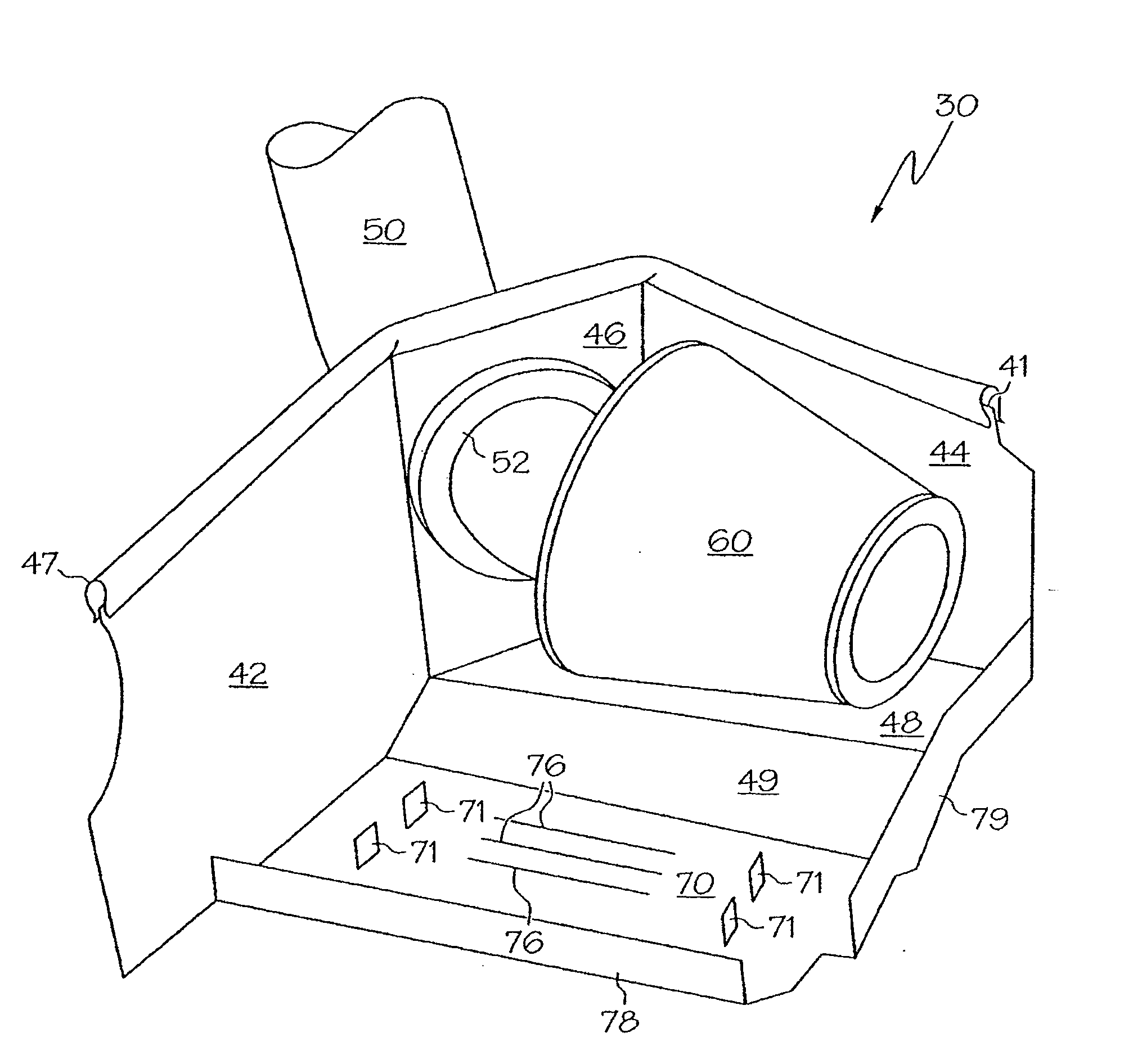
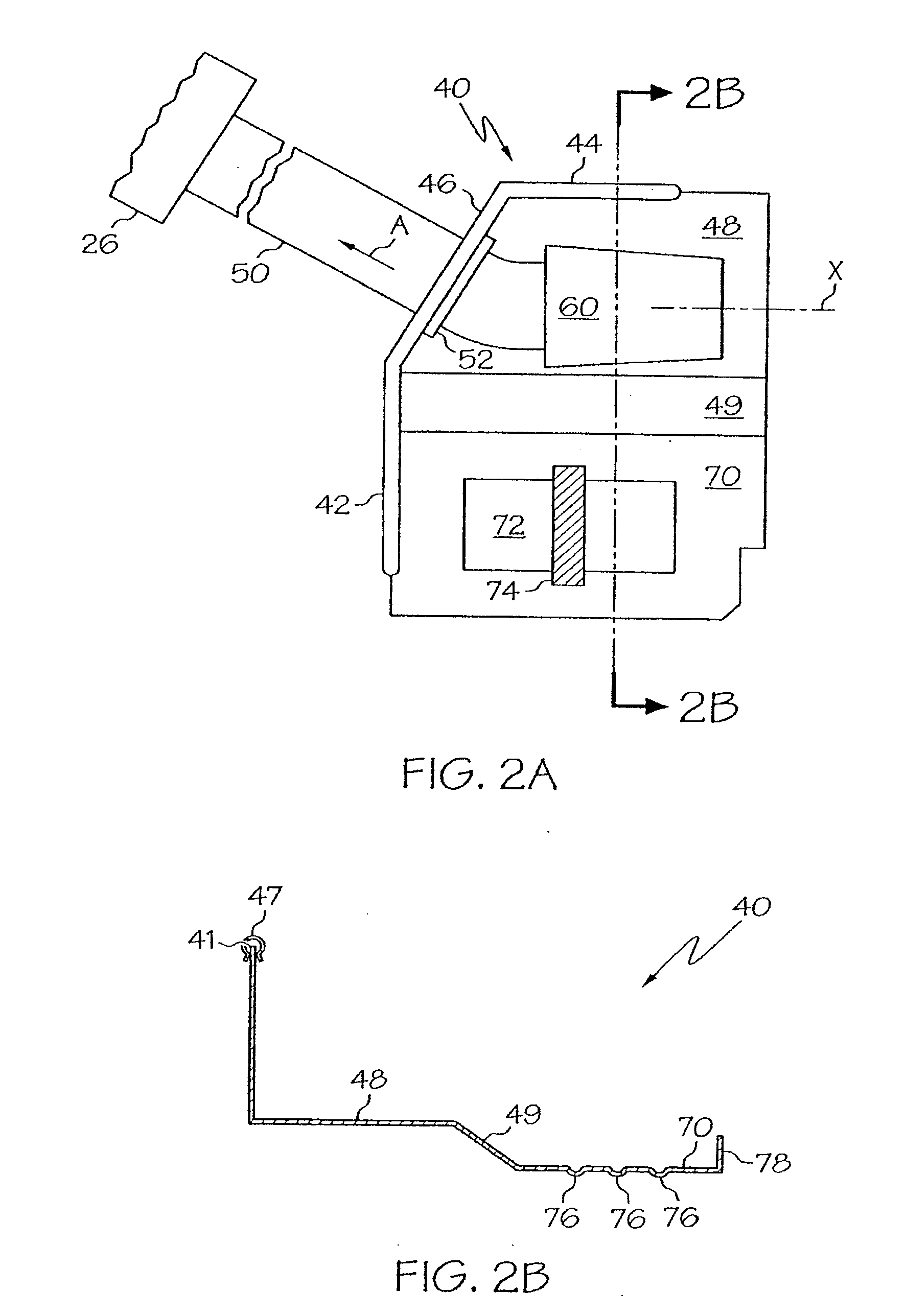
[0034] An embodiment of the present invention may be distinguished from the prior art in having, inter alia, a filter housing which may include first and second walls, and a third wall diagonally disposed between the first and second walls. The present invention may be further distinguished from the prior art in having an air intake tube affixed to, and extending through, the third wall. The present...


PUM

PropertyMeasurementUnit
diameteraaaaaaaaaa
diameteraaaaaaaaaa
diameteraaaaaaaaaa

Abstract

An apparatus for filtering air includes a filter housing and a battery tray integral with the filter housing. The battery tray may be coupled to the filter housing via a ramp. The filter housing may comprise a first wall, a second wall, and a third wall, wherein the third wall is diagonally disposed between the first and second walls. The apparatus may further include an air intake tube having an upstream portion affixed to the third wall, and a downstream portion configured for fluid communication with a turbocharger of a V8 Ford diesel truck. Methods for providing filtered air to a turbo-diesel internal combustion engine are also disclosed.

Description

CROSS-REFERENCE TO RELATED APPLICATIONS [0001] This application is a continuation of patent application Ser. No. 11 / 088,526, filed on Mar. 24, 2005 which in turn claims the benefit of U.S. Provisional Patent Application No. 60 / 634,044, filed on Dec. 7, 2004 and U.S. Provisional Patent Application No. 60 / 556,171, filed on Mar. 24, 2004, the contents of each said earlier application are incorporated herein by reference.BACKGROUND OF THE INVENTION [0002] This invention relates to air filtration systems for motorized vehicles, and in particular, to high performance air filtration systems for use with vehicles, such as Ford F-Series trucks having a V8, 7.3 L turbo-diesel engine. [0003] The function of an air intake filter is to remove particulate matter from the intake air, so that clean air is provided to the engine. The intake air stream flows from the influent, or “dirty,” side of the filter to the effluent, or “clean,” side of the filter, with the air filter extracting the unwanted p...

Claims


Application Information

Patent Timeline
Patent Type & Authority Applications(United States)
IPC IPC(8): B01D46/00B01D46/24B01D46/52F02M35/02F02M35/04
CPCB01D46/2403B01D46/521F02M35/04F02M35/02B01D2275/10
Inventor BAJZA, ERIC CHARLESNIAKAN, SHAHRIAR NICKZAMBRANO, SAUL DANIEL
Owner ADVANCED FLOW ENG
Learn More