Chain link plate with high strength

a chain link plate and high strength technology, applied in the field of chains, can solve the problem of inferior strength of chain link plates, and achieve the effect of high strength

Inactive Publication Date: 2007-08-09
KMC CHAIN INDUSTRIAL
View PDF10 Cites 24 Cited by
  • Summary
  • Abstract
  • Description
  • Claims
  • Application Information

AI Technical Summary

Benefits of technology

[0006]Therefore, the object of the present invention

Problems solved by technology

In such a configuration, the chain

Method used


Image

  • Chain link plate with high strength
  • Chain link plate with high strength
  • Chain link plate with high strength

Examples


Embodiment Construction

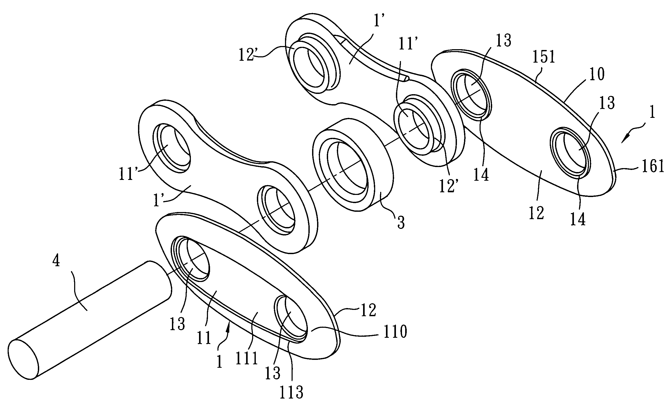
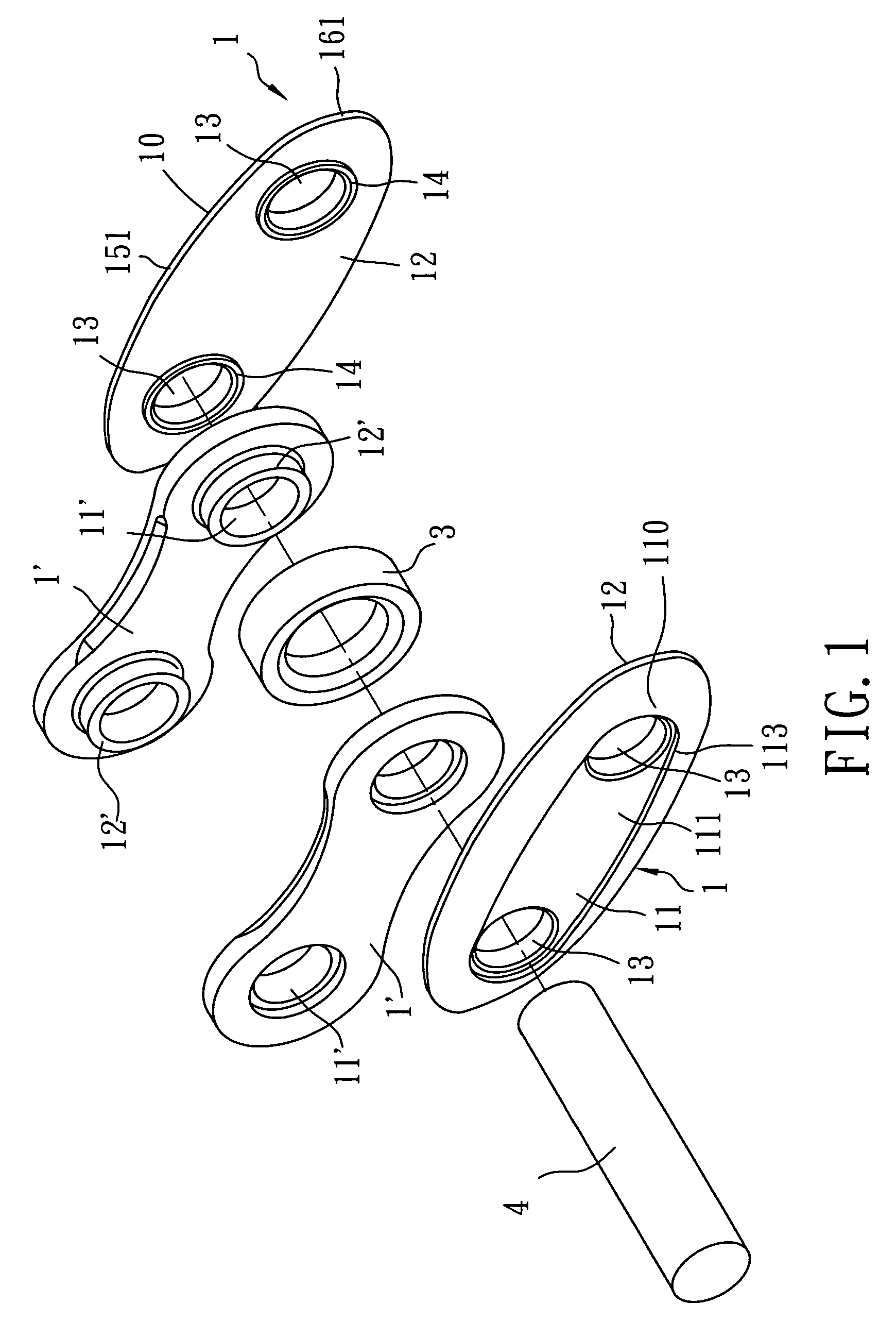
[0013]Referring to FIGS. 1 to 3, the preferred embodiment of a chain link plate 1 according to the present invention is shown to be an element of a chain unit. The chain unit is composed of a pair of the chain link plates 1 serving as outer chain link plates, a pair of inner chain link plates 1′, a connecting pin 4 and a roller 3. The inner chain link plates 1′ are disposed to face each other. Each inner chain link plate 1′ is formed with two through holes 11′ spaced apart from each other, and has two annular rings 12′ that extend toward the other inner chain link plate 1′ and that define respectively peripheries of the through holes 11′. The roller 3 is disposed between the inner chain link plates 1′ and are sleeved on two corresponding ones of the annular rings 12′ of the inner chain link plates 1′. The connecting pin 4 is inserted through the roller 3, two corresponding ones of the through holes 11′ in the inner chain link plates 1′ and the corresponding rings 12′ such that oppos...


PUM

PropertyMeasurementUnit
Thicknessaaaaaaaaaa
Widthaaaaaaaaaa
Areaaaaaaaaaaa

Abstract

A chain link plate includes an elliptical plate body having opposite first and second surfaces, and two mounting holes spaced apart from each other in a longitudinal direction of the plate body and extending from the first surface to the second surface. The plate body has a central longitudinal line that passes through centers of the mounting holes, and two transverse lines that pass respectively through the centers of the mounting holes and that are perpendicular to the central longitudinal line. The plate body has an intermediate juncture portion defined between the transverse lines, and opposite end portions integrally and respectively connected to opposite ends of the intermediate juncture portion. The intermediate juncture portion has a largest width greater than that of each of the end portions.

Description

CROSS-REFERENCE TO RELATED APPLICATION[0001]This application claims priority of Taiwanese Application No. 095202289, filed on Feb. 9, 2006.BACKGROUND OF THE INVENTION[0002]1. Field of the Invention[0003]The invention relates to chains, more particularly to a chain link plate with high strength.[0004]2. Description of the Related Art[0005]Conventional chains are composed of inner chain link plates, outer chain link plates, rollers and connecting pins. Each of the inner and outer chain link plates generally has a narrowed waist portion interconnecting integrally enlarged opposite end portions and having a width smaller than that of each end portion. Each end portion is formed with a through hole. In such a configuration, the chain link plates have inferior strength.SUMMARY OF THE INVENTION[0006]Therefore, the object of the present invention is to provide a chain link plate having high strength.[0007]According to the present invention, a chain link plate comprises:[0008]an elliptical p...

Claims


Application Information

Patent Timeline
IPC IPC(8): F16G13/06
CPCF16G13/06
Inventor WU, DANIEL
Owner KMC CHAIN INDUSTRIAL
Why Eureka
Try Eureka