Ejector refrigerant cycle device and control method thereof

a technology of ejector and refrigerant cycle, which is applied in the direction of refrigeration components, machine operation modes, lighting and heating apparatus, etc., can solve the problems of increasing the size of the evaporator and increasing the cost, and the size and cost of the whole ejector refrigerant cycle device is increased

Inactive Publication Date: 2007-08-09
DENSO CORP
View PDF7 Cites 22 Cited by
  • Summary
  • Abstract
  • Description
  • Claims
  • Application Information

AI Technical Summary

Benefits of technology

[0007] In view of the above-mentioned problems, an object of the present invention is to provide an ejector refrigerant cycle device which can prevent the press

Problems solved by technology

For this reason, the evaporator is required to have resistance to the pressure of the high-pressure refrigerant, which results in enlarging

Method used


Image

  • Ejector refrigerant cycle device and control method thereof
  • Ejector refrigerant cycle device and control method thereof
  • Ejector refrigerant cycle device and control method thereof

Examples


first embodiment

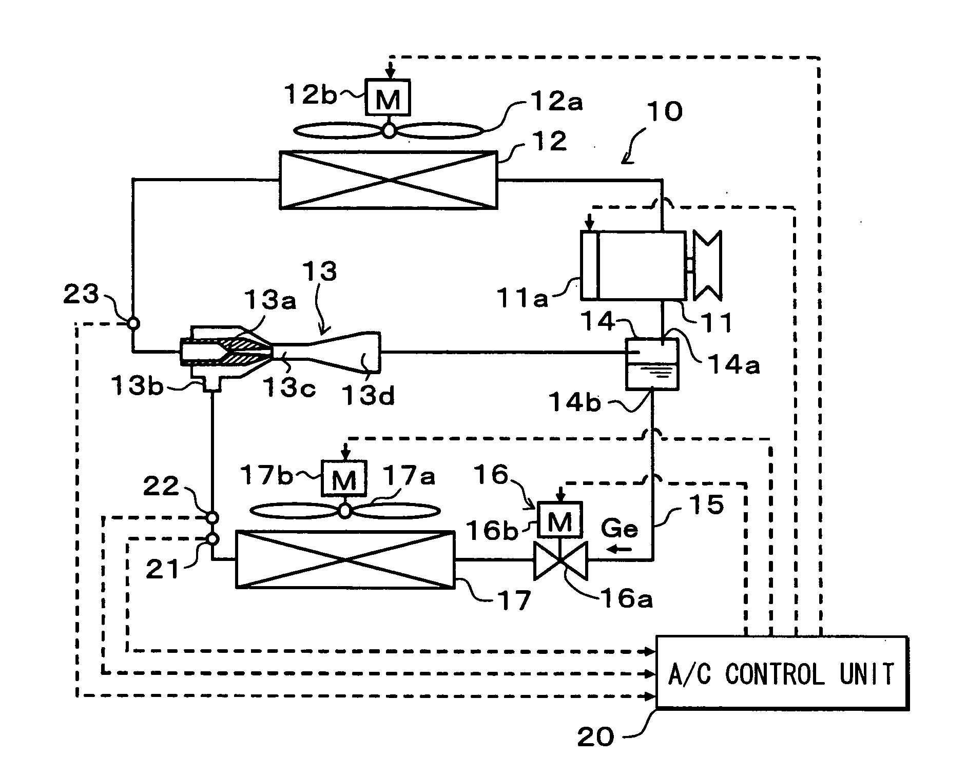
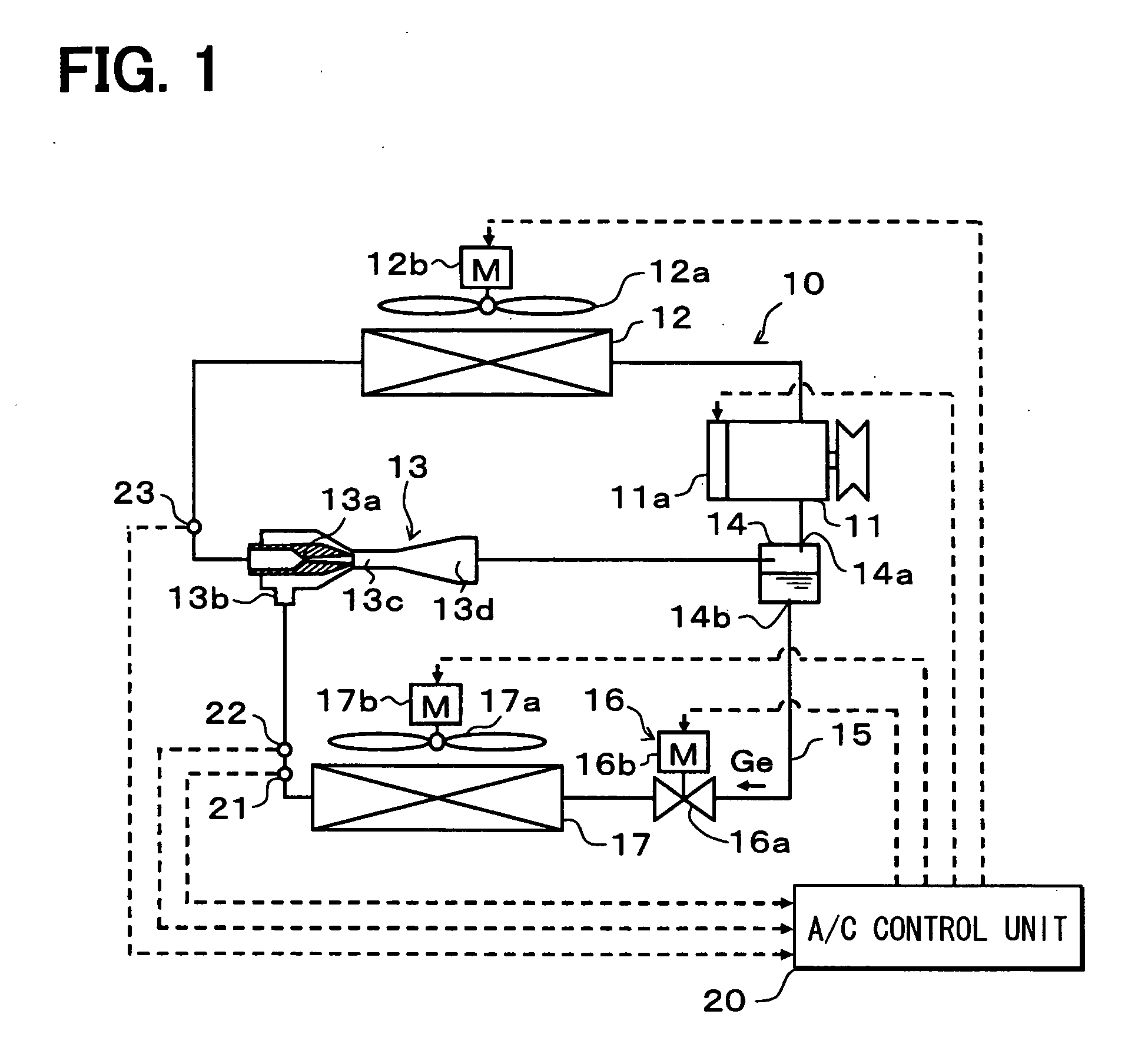
[0026] In this embodiment, refrigerant (e.g., carbon dioxide) in which a high-pressure side refrigerant pressure is higher than a supercritical pressure is used as the refrigerant of an ejector refrigerant cycle device. Thus, the ejector refrigerant cycle device of this embodiment constructs a supercritical refrigerant cycle.

[0027] First, in an ejector refrigerant cycle device 10, a compressor 11 draws, compresses and discharges refrigerant, and increases the pressure of refrigerant to a supercritical pressure in this embodiment. This compressor 11 has a driving force transmitted thereto from a vehicle running engine (not shown) via a pulley and a belt, thereby being rotated and driven. Moreover, in this embodiment, a well-known swash-plate type variable displacement compressor capable of controlling a discharge volume variably and continuously by a control signal from the outside is used as the compressor 11.

[0028] Here, the discharge volume means the geometric volume of an opera...

second embodiment

[0071] In the above-described first embodiment, refrigerant cycle is provided with the liquid-phase refrigerant passage 15 for connecting the liquid-phase refrigerant outlet 14b of the accumulator 14 to the refrigerant suction port 13b of the ejector 13, and the variable throttle mechanism 16 and the evaporator 17 are arranged in this liquid-phase refrigerant passage 15. In the second embodiment, however, as shown in FIG. 3, the liquid-phase refrigerant passage 15 is not provided but there is provided a branch passage 25 for branching the refrigerant flow at a branch point Z that is positioned between the downstream side of the radiator 12 and the upstream side of the nozzle portion 13a of the ejector 13.

[0072] This branch passage 25 is a refrigerant passage for connecting the branch point Z to the refrigerant suction port 13b of the ejector 13. In this embodiment, the variable throttle mechanism 16 is arranged in the branch passage 25, and the evaporator 17 is arranged on the down...


PUM


Abstract

An ejector refrigerant cycle device includes an ejector that has a nozzle portion for reducing pressure of refrigerant on a downstream side of a radiator to expand the refrigerant, and a refrigerant suction port from which refrigerant is drawn by a high-velocity refrigerant flow jetted from the nozzle portion, an evaporator that evaporates refrigerant and flows out the evaporated refrigerant to the refrigerant suction port, a flow amount changing unit that changes a refrigerant flow amount flowing into the evaporator, and a pressure abnormality detecting portion for detecting a pressure abnormality of a high-pressure refrigerant on an upstream side of the nozzle portion. In the ejector refrigerant cycle device, when the pressure abnormality detecting portion detects the pressure abnormality, the flow amount changing unit makes the refrigerant flow amount flowing into the evaporator larger than that in a normal pressure state of the high-pressure refrigerant.

Description

CROSS REFERENCE TO RELATED APPLICATION [0001] This application is based on Japanese Patent Application No. 2005-359093 filed on Dec. 13, 2005, the contents of which are incorporated herein by reference in its entirety. FIELD OF THE INVENTION [0002] The present invention relates to an ejector refrigerant cycle device having an ejector, and a control method of an ejector refrigerant cycle device. BACKGROUND OF THE INVENTION [0003] U.S. Pat. No. 6,837,069 (corresponding to JP-A-2004-53028) describes an ejector refrigerant cycle device that is so constructed as to avoid an abnormal increase in a high-pressure side refrigerant pressure in order to secure the reliability of refrigerant piping and functional parts which receive the high-pressure side refrigerant pressure of the cycle. [0004] In the ejector refrigerant cycle device of U.S. Pat. No. 6,837,069 (corresponding to JP-A-2004-53028), a branch point for branching a high-pressure refrigerant flow is provided on an upstream side of a...

Claims


Application Information

Patent Timeline
IPC IPC(8): F25B19/02F25B1/06
CPCF25B9/008F25B41/00F25B2600/2515F25B2341/0012F25B2400/23F25B2309/061B60H2001/3298
Inventor SUGIURA, TAKAYUKITAKEUCHI, HIROTSUGU
Owner DENSO CORP
Why Eureka
Try Eureka