Fence Post Driver and Remover

a technology for fence posts and drivers, applied in the field of fence post drivers and removers, can solve the problems of inability to remove fence posts, heavy drivers,

Inactive Publication Date: 2007-08-09
MASON ROBERT
View PDF30 Cites 27 Cited by
  • Summary
  • Abstract
  • Description
  • Claims
  • Application Information

AI Technical Summary

Benefits of technology

[0010]The instant invention may be used in a fence driving best mode and in a fence removing best mode. In the best mode of operation of the instant invention for driving fence posts into the ground, the instant invention is placed over the fence post so that the fence post extends into the stationary ram. In driving fence posts, the t-handle may be left loose or may be tightened to secure the fence post. In most instances, the t-handle is not tightened. The user then grasps the handles and repeatedly raises and lowers the sliding ram forcing the sliding ram to hammer onto the bottom collar. The force of the sliding ram hammering on the bottom collar is transferred through the stationary ram to the reinforced plug which is in turn affixed to the underside or inside of the top cap. The force is in turn transferred from the top cap to the top of the fence post or shaft hereby driving the fence post into the ground.
[0011]In the best mode of operation of the instant invention for removing fence posts from the ground, the instant invention is placed over the fence post so that the fence post extends into the stationary ram. In removing fence posts, the t-handle must be tightened to secure the fence post. The user then grasps the handles and repeatedly raises and lowers the sliding ram forcing the sliding ram to hammer up into the reinforced top cap. The force of the sliding ram hammering up into the top cap is transferred through the stationary ram to bottom collar, through the threaded aperture, through the t-handle to the fence thereby pulling the fence post shaft or stake upward and out of the ground.
[0012]There have thus been outlined, rather broadly, the more important features of the invention in order that the detailed description thereof that follows may be better understood, and in order that the present contribution to the art may be better appreciated. There are, of course, additional features of the invention that will be described hereinafter and which will form the subject matter of the claims appended hereto.

Problems solved by technology

First, the driver is typically very heavy.
Second, at the initial installation of a fence post, the driver must be held high over the fence post to gain proper leverage to drive the post.
Third, the drivers are able to only install fence post, and are not capable of removing fence posts.

Method used


Image

  • Fence Post Driver and Remover
  • Fence Post Driver and Remover
  • Fence Post Driver and Remover

Examples


Embodiment Construction

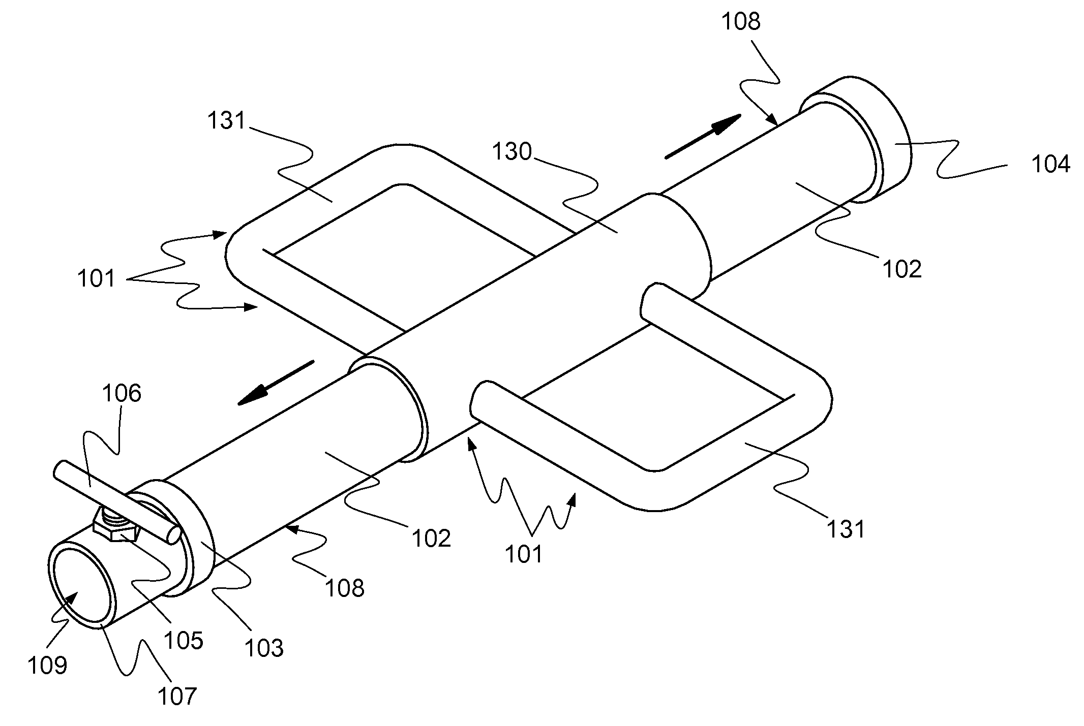
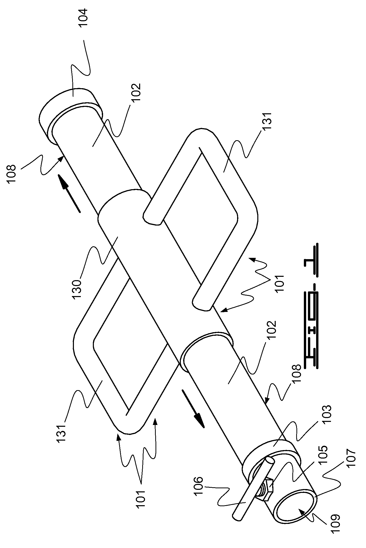
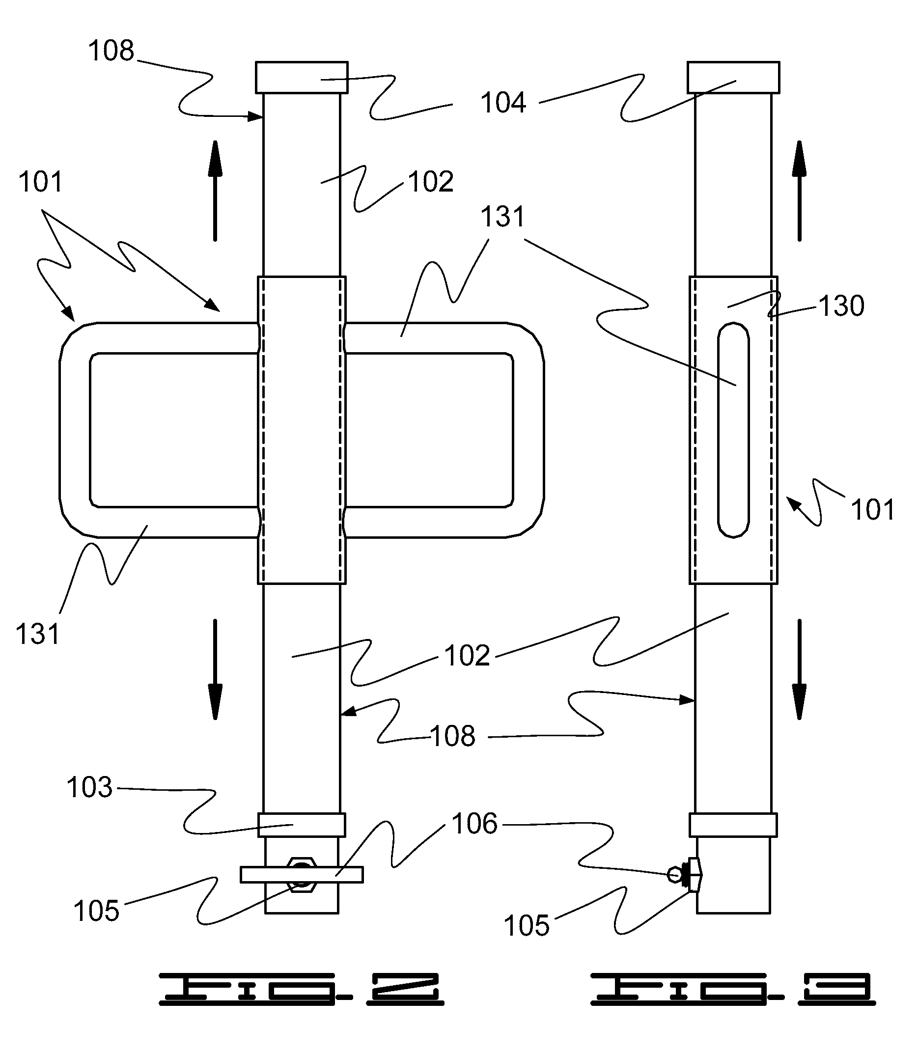
[0020]The instant invention, the fence post driver and remover, is comprised of a sliding ram 130 and a stationary ram 102. The instant invention is suitable to drive any elongated shaft into the ground, including, but not limited to, anchors, piping, grounding rods, round fencing, and t-post fencing. The stationary ram 102 is essentially a hollow cylinder. In addition, the instant invention can be resized to accommodate any sized elongated shaft, including, but not limited to, anchors, piping, grounding rods, round fencing, and t-post fencing, to be made more transportable for specialized use by adjusting the diameter of the hollow cylinder formed by the stationary ram 102.

[0021]To begin operation of the instant invention the stationary ram 102 is placed over the end of the fence post or any other shaft. That is, for operation of the instant invention the fence post slides into the hollow formed by the stationary ram 102 so that the instant invention rests on top of the top end of ...


PUM


Abstract

The instant invention, the fence post driver and remover, is comprised of a sliding ram and a stationary ram. The stationary ram is a hollow cylinder. To begin operation of the instant invention the stationary ram is placed over the end of the fence post. That is, for operation of the instant invention the fence post slides into the hollow formed by the stationary ram so that the instant invention rests on top of the top end of the fence post. The instant invention may be used to both drive fence posts and remove fence posts. In addition, the instant invention may be used in conjunction with any elongated objects to be driven into or removed from the ground.

Description

CROSS-REFERENCES TO RELATED APPLICATIONS[0001]This application claims the benefit of U.S. Provisional Application No. 60 / 765,576 filed on Feb. 6, 2006 titled “Fence post driver and remover.” The entire contents of provisional application 60 / 765,576 are incorporated herein by reference.STATEMENT REGARDING FEDERALLY SPONSORED RESEARCH OR DEVELOPMENT[0002]Not applicable.THE NAMES OF THE PARTIES TO A JOINT RESEARCH AGREEMENT[0003]Not applicable.REFERENCE TO A “SEQUENCE LISTING,” A TABLE, OR A COMPUTER PROGRAM LISTING APPENDIX SUBMITTED ON A COMPACT DISC AND AN INCORPORATION-BY-REFERENCE OF THE MATERIAL ON THE COMPACT DISC[0004]Not applicable.BACKGROUND OF THE INVENTION[0005]It is a common chore for ranchers, farmers and homeowners to install fencing on their property. One of the most economical styles of fencing is the t-post. T-post fencing requires the installation of the t-posts along the fence line, and installation of these posts is the first and most time consuming of the steps to...

Claims


Application Information

Patent Timeline
Patent Type & Authority Applications(United States)
IPC IPC(8): B25D11/00
CPCB25D1/16
Inventor MASON, ROBERT
Owner MASON ROBERT
Why Eureka
Try Eureka