
Tactile and force feedback device

a force feedback and tactile technology, applied in the field of tactile feedback apparatus, can solve the problems of difficult interactive use, large size of the solenoid element, and inability to mount on a small-sized device, and achieve the effect of enhancing tactile feedback

Inactive Publication Date: 2007-08-09
SONY CORP +1
View PDF4 Cites 75 Cited by
  • Summary
  • Abstract
  • Description
  • Claims
  • Application Information

AI Technical Summary

Benefits of technology

[0027] According to the present invention, there may be provided a tactile feedback apparatus, particularly applicable to a human interface control device, such as a button or a controller, and a system including this tactile feedback apparatus as a human interface control apparatus.
[0028] According to the present invention, there may be provided a tactile feedback apparatus that is able to present larger tactile feedback that may readily be recognized by the user.
[0029] According to the present invention, there may be provided a tactile feedback apparatus in which the force applied by the user may be correlated with the tactile feedback.

Problems solved by technology

In such conventional control devices, the sort of the tactile feedback may not be changed, while it is not possible to change the tactile sense on actuation by the user of the interfacing element, using a computer application program, for presenting the sense of actuation of the user interface element more effectively to the user.
Moreover, the solenoid element is so large in size that it cannot be mounted on a small-sized device, such as joystick of a controller for a game or a button used on a camera.
However, the motor for generating the vibrations is extremely slow in reaction and hence is difficult to use for interactive usage in need of prompt response.
Moreover, for a usage such as for a game, vibrations at higher frequencies do not prove to be effective feedback.
The devices used in these techniques are large in size and weight and hence are difficult to use on a small-sized site on a game controller.
In addition, only a highly limited tactile pattern may be generated by these devices.
Moreover, the tactile bandwidth is narrow due to the force of inertia of the motor.
For these reasons, the usage of these devices is mainly limited to force feedback devices.
With the technique disclosed in this Laid-open Patent Publication, the amplitude of vibrations of the piezoelectric elements is small, while there lacks the disclosure of a mechanism for generating larger tactile feedback.

Method used


Image

  • Tactile and force feedback device
  • Tactile and force feedback device
  • Tactile and force feedback device

Examples


Embodiment Construction

[0037] Referring to the drawings, preferred embodiments of the present invention will be explained in detail.

(1) System Structure

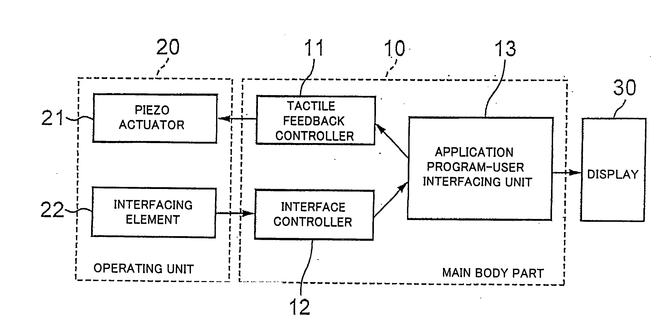
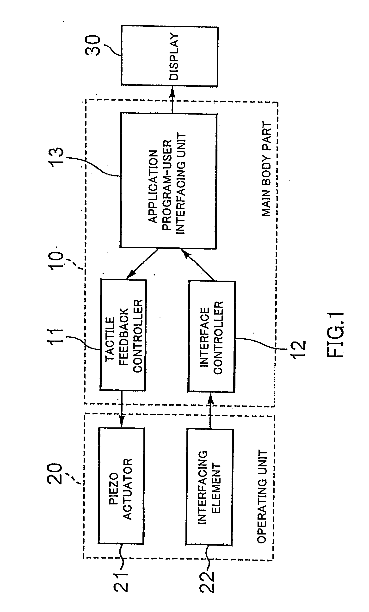
[0038] Referring to FIG. 1, an example of system structure employing the present invention will be explained. As shown in FIG. 1, the present system includes a main body part 10, an operating unit 20 on which a user acts by way of an inputting operation for interfacing with the main body part 10, and a display part 30 for demonstrating an image consistent with the current state of the interface and the application program.

[0039] The operating unit 20 includes an interfacing element 22, accepting the user's inputting operation, and a piezo actuator 21 for generating tactile feedback for a user performing an inputting operation on the operating unit 20. Details and a concrete structure of the piezo actuator 21 will be explained subsequently. The interfacing element 22 is any optional user interface controller, such as a button or a joystick.

[0040] It is...


PUM


Abstract

Disclosed is a system including a tactile feedback device with which a user can sense the tactile force that is applied by the user on actuating a button or the like. The system includes a main body part (10), an operating unit (20) on which the user acts for inputting for interfacing with the main body part, and a display part (30) for demonstrating an image consistent with the current state of an interface program and an application program. The operating unit includes an interfacing element (22) for accepting an inputting operation from the user and a piezo actuator (21) for presenting a tactile feedback to the user performing the inputting operation on the operating unit. The piezo actuator is mounted on the interfacing element.

Description

TECHNICAL FIELD [0001] This invention relates to an apparatus for presenting tactile feedback for a user. More particularly, the present invention relates to a tactile feedback apparatus for a human interface control device directly acted on by a user's finger, such as a switch, a button or a joystick. [0002] The present invention contains subject matter related to Japanese Patent Application JP 2003-287988, filed in the Japanese Patent Office on Aug. 6, 2003, the entire contents of which being incorporated herein by reference. BACKGROUND ART [0003] The force feedback is among critical elementary functions for a variety of control devices, such as buttons or joysticks. A rubber pad, provided on a mechanical switch or mechanism, is routinely used for presenting such tactile feedback. In such conventional control devices, the sort of the tactile feedback may not be changed, while it is not possible to change the tactile sense on actuation by the user of the interfacing element, using ...

Claims


Application Information

Patent Timeline
Patent Type & Authority Applications(United States)
IPC IPC(8): G09G5/00A63F13/24A63F13/285G06F3/00G06F3/01H01H3/12H01H9/16H01H25/04
CPCA63F13/02A63F13/06H01H2215/052G06F3/016G06F2203/013A63F2300/1037A63F13/533A63F2300/308A63F2300/1012A63F13/24A63F13/28A63F13/285A63F2300/302A63F2300/204A63F13/212A63F2300/1043A63F13/92
Inventor POUPYREV, IVANMARUYAMA, SHIGEAKIDANIEL, TYLER
Owner SONY CORP
Features
  • Generate Ideas
  • Intellectual Property
  • Life Sciences
  • Materials
  • Tech Scout
  • Unparalleled Data Quality
  • Higher Quality Content
  • 60% Fewer Hallucinations
Learn More