
Endoscopy system and a pressure transmitting connector for said system

a technology of endoscope and connector, which is applied in the direction of laproscope, medical devices, sensors, etc., can solve the problems of artificially high pressure drop of sensed pressure, erroneous determination of pressure,

Active Publication Date: 2007-08-09
FUTURE MEDICAL SYST
View PDF15 Cites 4 Cited by
  • Summary
  • Abstract
  • Description
  • Claims
  • Application Information

AI Technical Summary

Benefits of technology

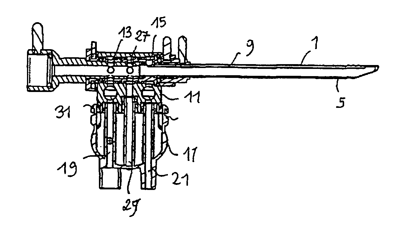
[0010] Preferably, the branch-off path is placed downstream of the coupling path for coupling to the irrigation channel relative to the transport of the irrigating fluid and upstream of the coupling path for coupling to the outflow channel, respectively, relative to the transport of the outflow fluid, and in that an irrigation tap is provided for closing or opening the coupling path to the irrigation channel, upstream of the branch-off path, and an outflow tap is provided for closing or opening the coupling path to the outflow channel, respectively, downstream of the branch-off path. Advantageously, this arrangement makes it possible for the pressure in the joint to be always checked, even when the flow of the fresh physiological saline in the irrigation channel is interrupted by closing the irrigation tap. The same applies when the soiled physiological saline flowing in the outflow channel is considered.
[0012] Advantageously, the connector includes a second communication path. Preferably, the branch-off path is placed between the two communication paths. This arrangement makes it possible to connect the coupling ring to the communication path for irrigation, to the blind path and to the communication path for the outflow in a single operation, while still allowing pressure sensing in the blind path and one or other of the communication paths.

Problems solved by technology

These arrangements have the drawback of resulting in the pressure being erroneously determined under certain operating conditions, for example should by accident there be a sharp bend between the pressure sensor and the coupling ring.
However, the sensed pressure remains subject to an artificially high pressure drop in the coupling path for coupling the communication path of the connector to the irrigation channel of the cannula.
This may be due to a foreign body present in the coupling path of the coupling ring and partially obstructing the flow of physiological saline in the irrigation channel.

Method used


Image

  • Endoscopy system and a pressure transmitting connector for said system
  • Endoscopy system and a pressure transmitting connector for said system
  • Endoscopy system and a pressure transmitting connector for said system

Examples


Embodiment Construction

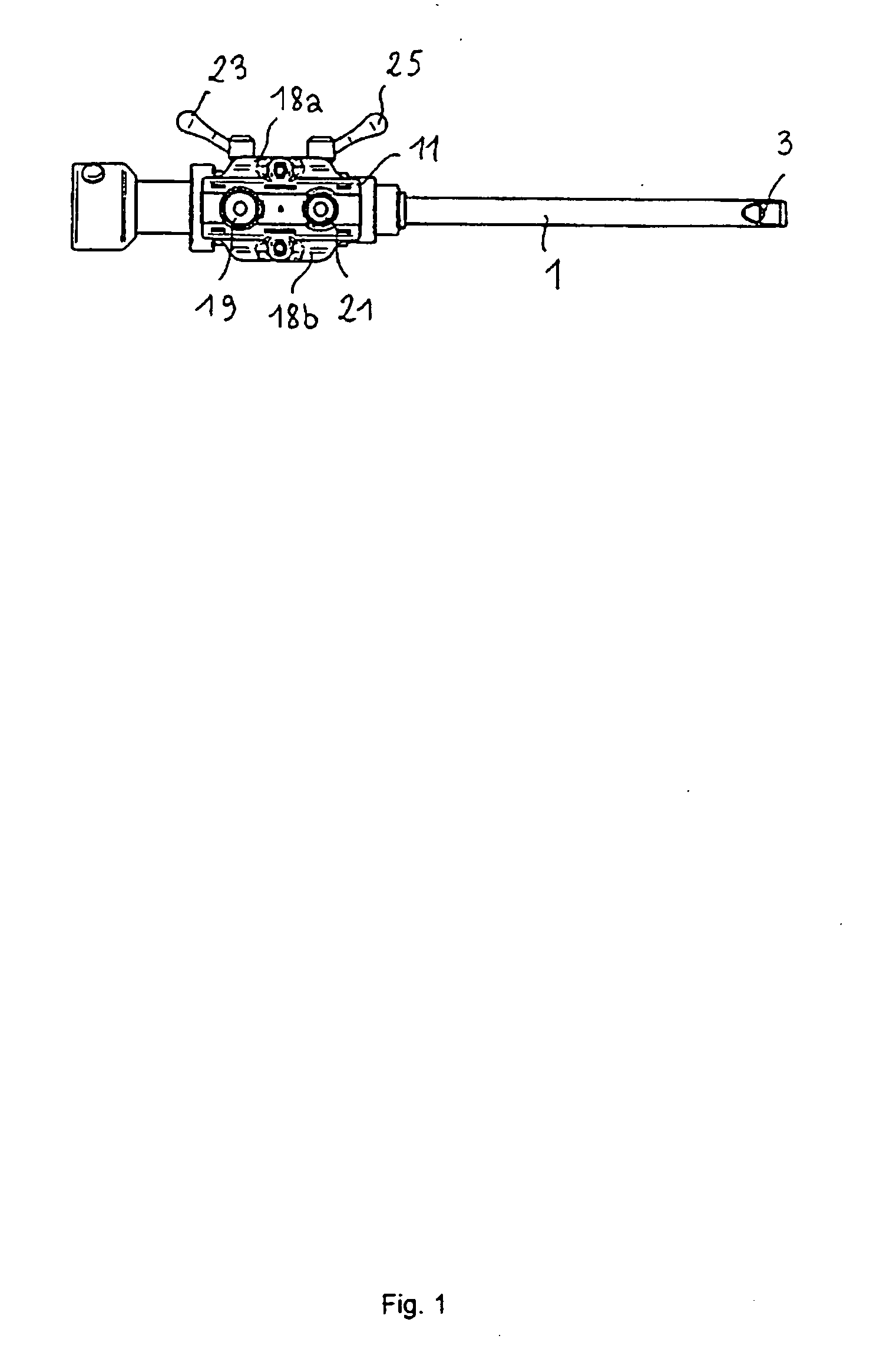
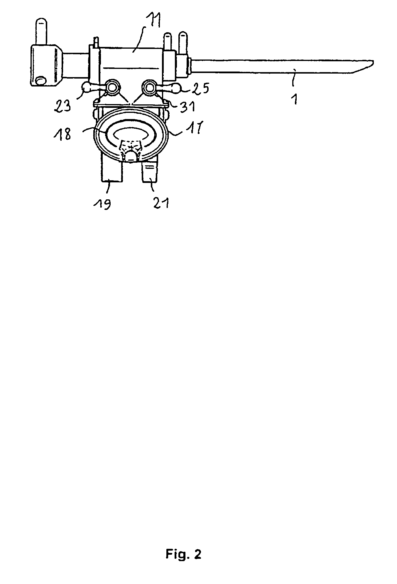
[0020] An endoscopy system comprises (FIGS. 1 to 4) a cannula 1 for housing an endoscope 3 and for forming, between the cannula 1 and the endoscope 3, an irrigation channel 5. In the embodiment chosen to illustrate the invention, the irrigation channel 5 is formed between the endoscope 3 and a tube 7 internal to the cannula 1, and an outflow channel 9 is formed between the internal tube 7 and the cannula 1. However, the invention also applies to a cannula having only the irrigation channel or only the outflow channel.

[0021] A coupling ring 11 is mounted around the cannula 1 in order to communicate with the irrigation channel 5 and the outflow channel 9. A first coupling path 13 communicates with the irrigation channel 5. A second coupling path 15 communicates with the outflow channel 9.

[0022] A connector 17 is mounted on the coupling ring 11. It comprises a first communication path 19, for communicating with the first coupling path 13 for coupling to the irrigation channel 5 and a...


PUM


Abstract

The inventive endoscopy system includes a cannula for arranging an endoscope and forming, between said cannula and endoscope, an irrigation or aspiration channel for transporting an irrigation or aspiration fluid, respectively, a connection ring mounted around the cannula and provided with a connection channel connectable to the irrigation or aspiration channel, respectively and a connector which is mounted on the connection ring and includes a transport channel with the connection channel and a first pressure sensor for detecting pressure in the transport channel. The connection ring is provided with a bypass circuit connectable to the irrigation or aspiration channel, respectively and the connector including a dead channel connectable to the bypass circuit and a second pressure sensor for detecting pressure in the dead channel.

Description

TECHNICAL FIELD [0001] The invention relates to an endoscopy system comprising more particularly a cannula for housing an endoscope and for forming, between the cannula and the endoscope, an irrigation channel or an outflow channel, and including a coupling ring mounted around the cannula and provided with a coupling path for communicating with the irrigation or outflow channel. PRIOR ART [0002] Such an endoscopy system is described for example by the documents U.S. Pat. No. 5,037,386 and U.S. Pat. No. 6,086,542. It is used in joint arthroscopy, and more particularly in knee arthroscopy. The endoscope is connected to a video screen for displaying the joint. The irrigation or outflow channel makes it possible to create a circulation of physiological saline for keeping the medium in front of the endoscope optically clear and for bathing the joint. The circulation is provided by a pump connected to a reservoir and outputting into a tubing connected to the irrigation channel or to the o...

Claims


Application Information

Patent Timeline
Patent Type & Authority Applications(United States)
IPC IPC(8): A61M5/178A61B1/015A61B1/12A61B1/317
CPCA61B1/015A61B1/317A61B1/12
Inventor FRANCISCO, ANDREJANIN, PATRICKPASCUAL, THIERRYDIAS, ARMANDO
Owner FUTURE MEDICAL SYST
Learn More