Method for calibrating a lighting control system that facilitates daylight harvesting

a technology of lighting control system and automatic calibration, which is applied in the field of automatic calibration of lighting control system, can solve the problems of system disablement, user annoyance and system failure, installation and maintenance of daylight harvesting system, etc., and achieve the effect of reducing the visual impact of changes

Active Publication Date: 2007-08-09
RGT UNIV OF CALIFORNIA
View PDF10 Cites 135 Cited by
  • Summary
  • Abstract
  • Description
  • Claims
  • Application Information

AI Technical Summary

Benefits of technology

[0018] In a variation on this embodiment, the system uses a ramping mechanism that gradually changes the light output of the lighting system to minimize the visual impact of the changes to the light output.

Problems solved by technology

However, installing and maintaining daylight-harvesting systems can involve substantial expense and effort.
For instance, the control system for a daylight-harvesting system may originally be calibrated by a human technician upon installation, but lose calibration over time due to changes in the area being illuminated and / or aging of the lighting system.
Ongoing manual calibration can involve considerable expense, while an uncalibrated lighting system may operate improperly, and can potentially lead to user annoyance and system disablement, with a resulting loss of energy savings.

Method used


Image

  • Method for calibrating a lighting control system that facilitates daylight harvesting
  • Method for calibrating a lighting control system that facilitates daylight harvesting
  • Method for calibrating a lighting control system that facilitates daylight harvesting

Examples


Embodiment Construction

[0048] The following description is presented to enable any person skilled in the art to make and use the invention, and is provided in the context of a particular application and its requirements. Various modifications to the disclosed embodiments will be readily apparent to those skilled in the art, and the general principles defined herein may be applied to other embodiments and applications without departing from the spirit and scope of the present invention. Thus, the present invention is not limited to the embodiments shown, but is to be accorded the widest scope consistent with the claims.

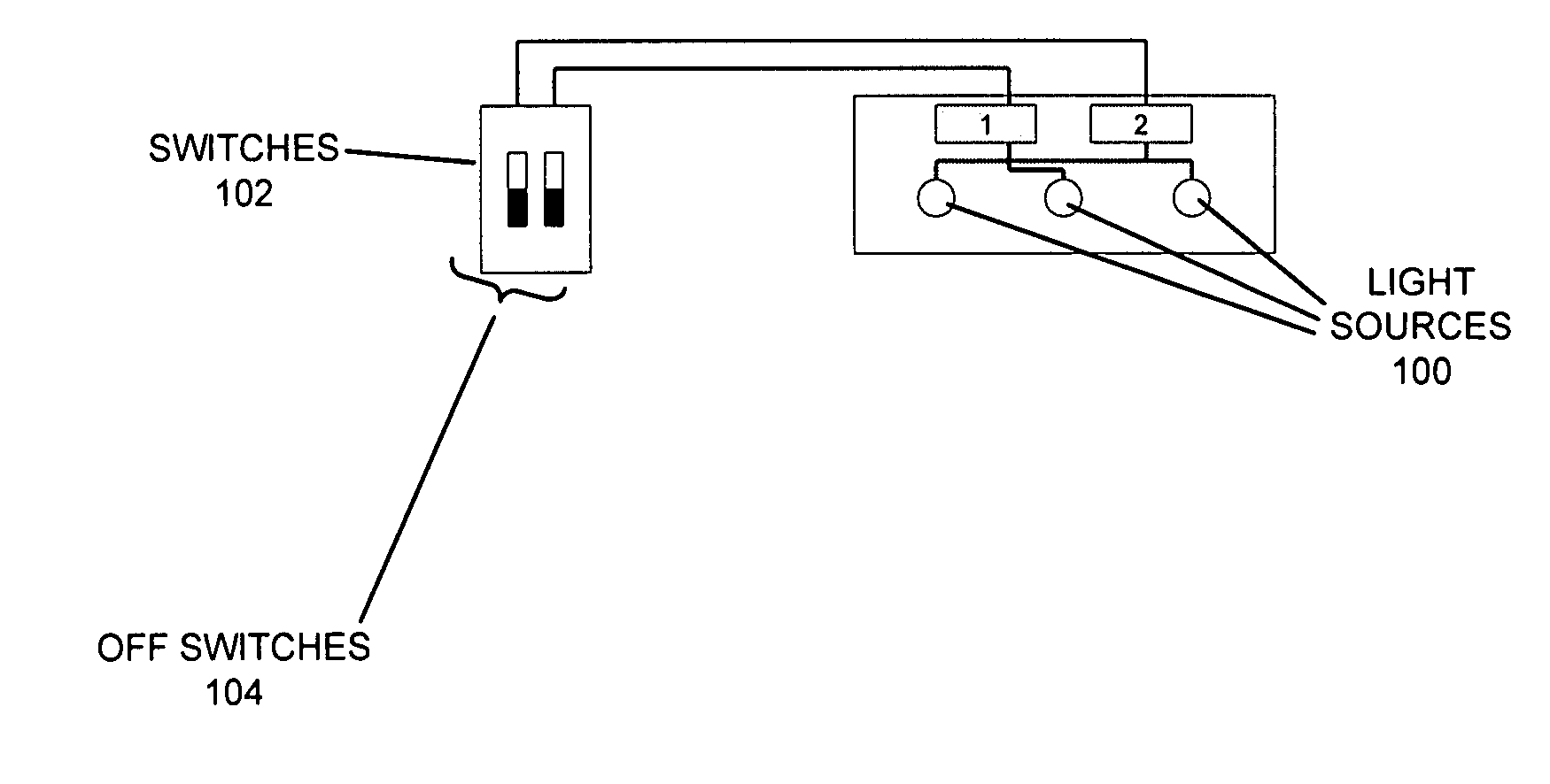
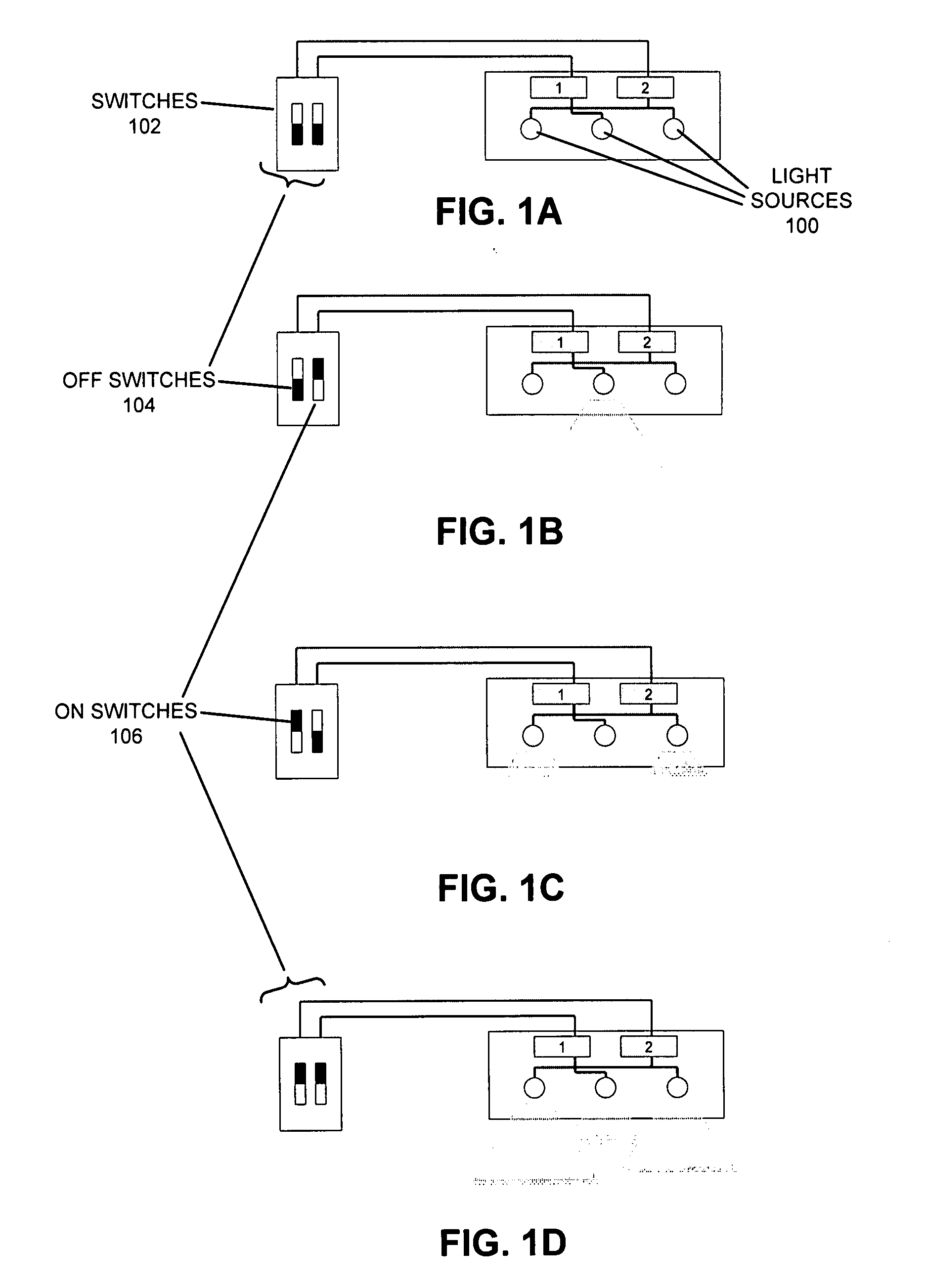
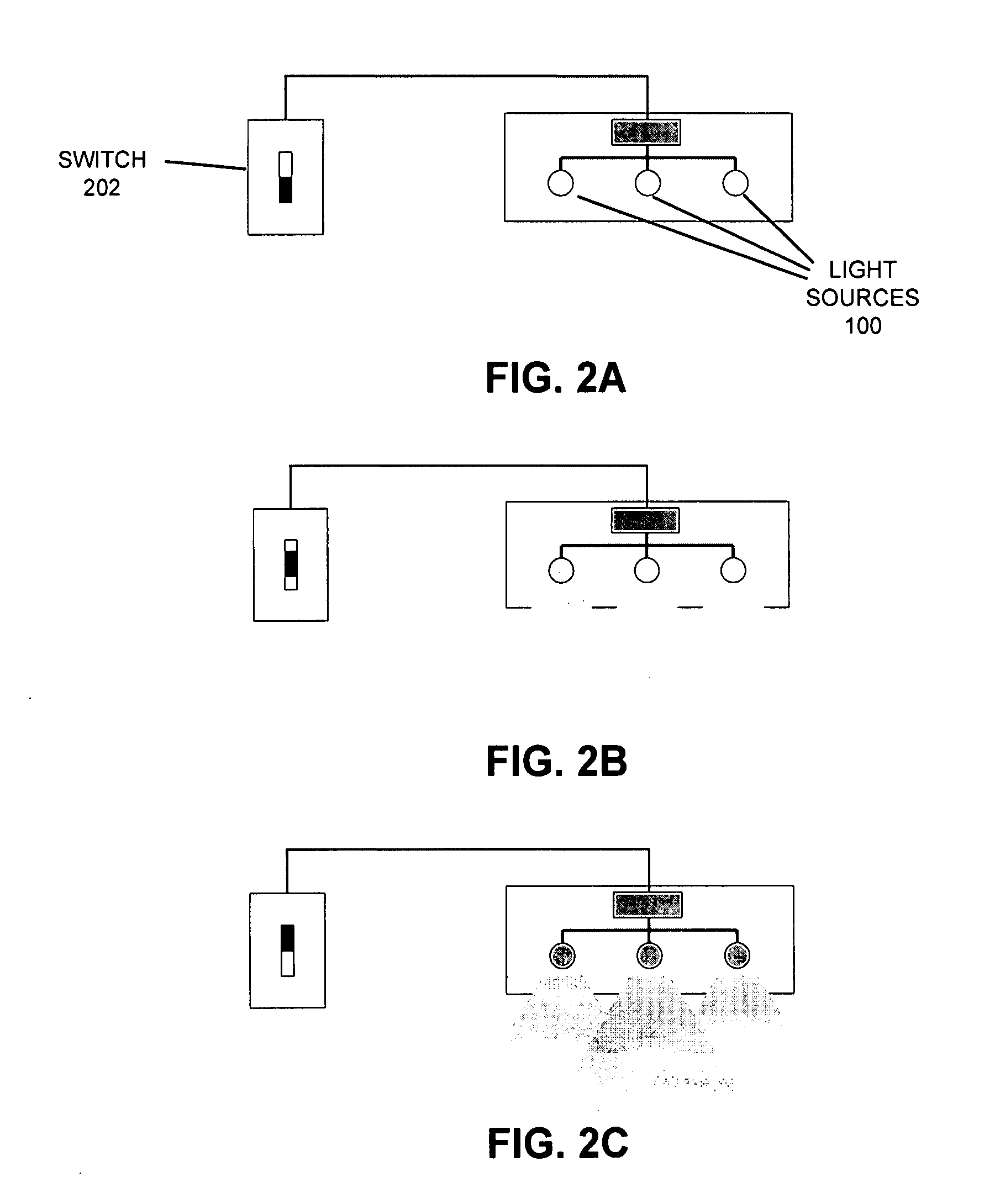
Daylight Harvesting Using Switching

[0049] Daylight work-place illuminance measurements in north-facing office spaces demonstrate that switching and / or dimming lights can be very effective in reducing energy usage in areas next to windows. These techniques can provide adequate daylight even on foggy, overcast winter days. Switching involves turning on / off one or more light elements in a mu...


PUM


Abstract

One embodiment of the present invention provides a system for calibrating a lighting control system. The lighting control system is a daylight-harvesting system that controls the output of the lighting system based on available daylight and/or other light sources to reduce energy usage while providing lighting for an area. The lighting system includes multi-level lighting capabilities for one or more light sources. First, the system measures the light levels for the area when the lighting system: is turned on at a high energy-level; is turned on at an intermediate energy-level; and is turned off. The system determines from these measured light levels the light output of the lighting system in the different states. Then, during operation, the system measures a present light level for the area. The system then adjusts the light output of the lighting system for the area based on a lighting control parameter (e.g an on set-point and an off set-point pair), the present light output of the lighting system, and the present light level for the area.

Description

RELATED APPLICATION [0001] This application claims priority under 35 U.S.C. section 119(e) to U.S. Provisional Application Ser. No. 60 / 771,770, entitled “Dual Photo-Sensor Dimming Daylight Controls,” by inventors Konstantinos Papamichael and Keith Graeber, filed on 08 Feb. 2006, the contents of which are herein incorporated by reference (Attorney Docket No. UC06-277-1 PSP).COLOR DRAWINGS [0002] The patent or application file contains at least one drawing executed in color. Copies of this patent or patent application publication with color drawing(s) will be provided by the Office upon request and payment of the necessary fee. BACKGROUND [0003] 1. Field of the Invention [0004] The present invention relates to lighting systems. More specifically, the present invention relates to the process of automatically calibrating a lighting control system that facilitates daylight-harvesting. [0005] 2. Related Art [0006] Most commercial spaces with windows receive enough daylight to at least par...

Claims


Application Information

Patent Timeline
Patent Type & Authority Applications(United States)
IPC IPC(8): G01R35/00
CPCF21S13/14F21V23/0435F21V23/0442Y02B20/46H05B37/0227H05B37/0272H05B37/0218H05B47/11H05B47/19H05B47/125Y02B20/40H05B47/115
Inventor PAPAMICHAEL, KONSTANTINOSGRAEBER, KEITHPAGE, ERIKSIMINOVITCH, MICHAEL
Owner RGT UNIV OF CALIFORNIA
Why Eureka
Try Eureka