Low visual impact labeling method and system

a labeling method and low visual impact technology, applied in the field of low visual impact labeling method and system, can solve problems such as problems that are often encountered, system limitations, mechanical and imaging problems, etc., and achieve the effect of reducing the visual impact of the label

Inactive Publication Date: 2005-10-20
MONDIE GEORGE R
View PDF16 Cites 11 Cited by
  • Summary
  • Abstract
  • Description
  • Claims
  • Application Information

AI Technical Summary

Benefits of technology

[0013] In another aspect, a machine readable indicia is formed on a plurality of labels from a light polarizing material applied over a reflective material that reflects light through the light polarizing material that can be filtered to produce a plurality of images. The machine readable indicia is reproducible by electronically comparing the images. The labels are applied to articles thereby enabling automated identification of the articles.
[0014] In this respect, automated identification of the articles includes (1) exposing the machine readable indicia to a source of light, (2) dividing light reflected from the indicia into a plurality of beams, (3) filtering each of a plurality of the beams through a polarized filter offset from each of the other filters by a predetermined angle, (4) generating an electronic image from each of the filtered beams with a detector, and (5) comparing at least one of the electronic images to at least one other of the electronic images to reproduce an image corresponding to the indicia. In yet another aspect, the light polarizing material and the reflective material are transparent to visible light to minimize the visual impact of the label on the article.
[0019] In this regard, the labels are exposed to a light source and the reflected light is separated with a beam splitter into a plurality of beams. Each of the plurality of beams is directed through a polarized filter and each filter is rotated with respect to each of the other filters by a predetermined angle, for example 60°. A detector such as a charged coupled array is used to generate an electronic image from each of the filtered beams and the electronic images are then compared to each of the other electronic images to isolate the image reflected from the indicia. In mail processing applications, the machine readable indicia may be a bar code such as Post Net code or a similar code including destination information for the mail piece. The system may also utilize materials which function as indicated only in infra-red or ultra-violet light so that the indicia and / or the substrate may be transparent to visible light, further reducing the visual impact of the indicia relative to the cover of the mail piece.

Problems solved by technology

Such systems have been proven extremely effective in sorting large volume mail flows, but these systems have limitations.
Automated processing of presorted flats, such as magazines and catalogues presents certain mechanical and imaging problems not encountered in connection with automated processing of letters.
Although in many cases these mail pieces will have a user-applied postnet bar code, problems are often encountered in locating the coded region of interest (ROI) on the cover of the flat.
These problems include poor contrast ratios and partial obscuration due to printed backgrounds, label skew (rotation from horizontal or vertical alignment), and the large amount of printed information which often appears on the covers, including text and other bar codes, which tends to confuse high-speed algorithmic approaches to ROI finding.
However, a large percentage of the volume of flat mail consists of magazines and catalogues for which this is not a good solution.
High quality paper, elaborate design, layout and expensive reproduction techniques escalate the cost of catalogues and brochures that may be summarily discarded by the recipient.
Consequently, there is a great deal of resistance on the part of the distributors of such catalogues and magazines to any printing or labeling of the publications cover that might tend to detract from the cover's appearance and its visual impact on the consumer.
Attempts to use fluorescent inks have met with little success due to problems with long drying times for such inks, smearing of the ink and poor contrast ratios with respect to the underlying substrate.
The latter problem is associated with papers having high fluorescence, i.e., recycled papers.

Method used


Image

  • Low visual impact labeling method and system
  • Low visual impact labeling method and system
  • Low visual impact labeling method and system

Examples


Embodiment Construction

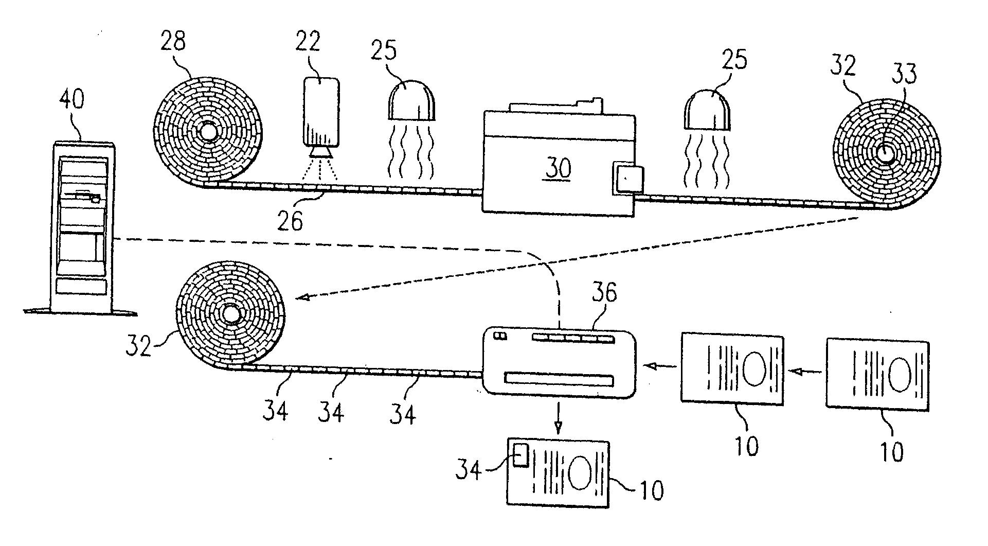
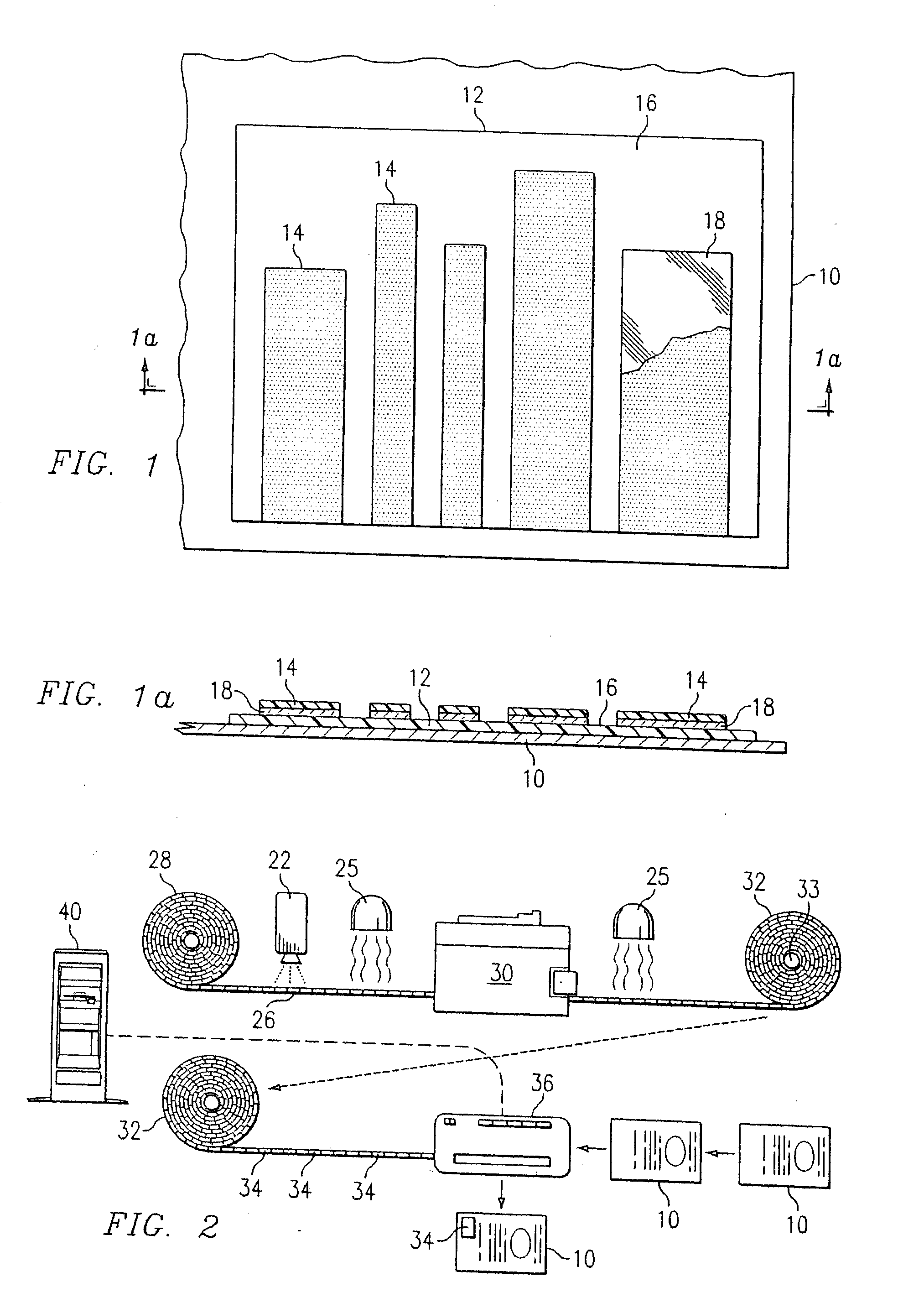
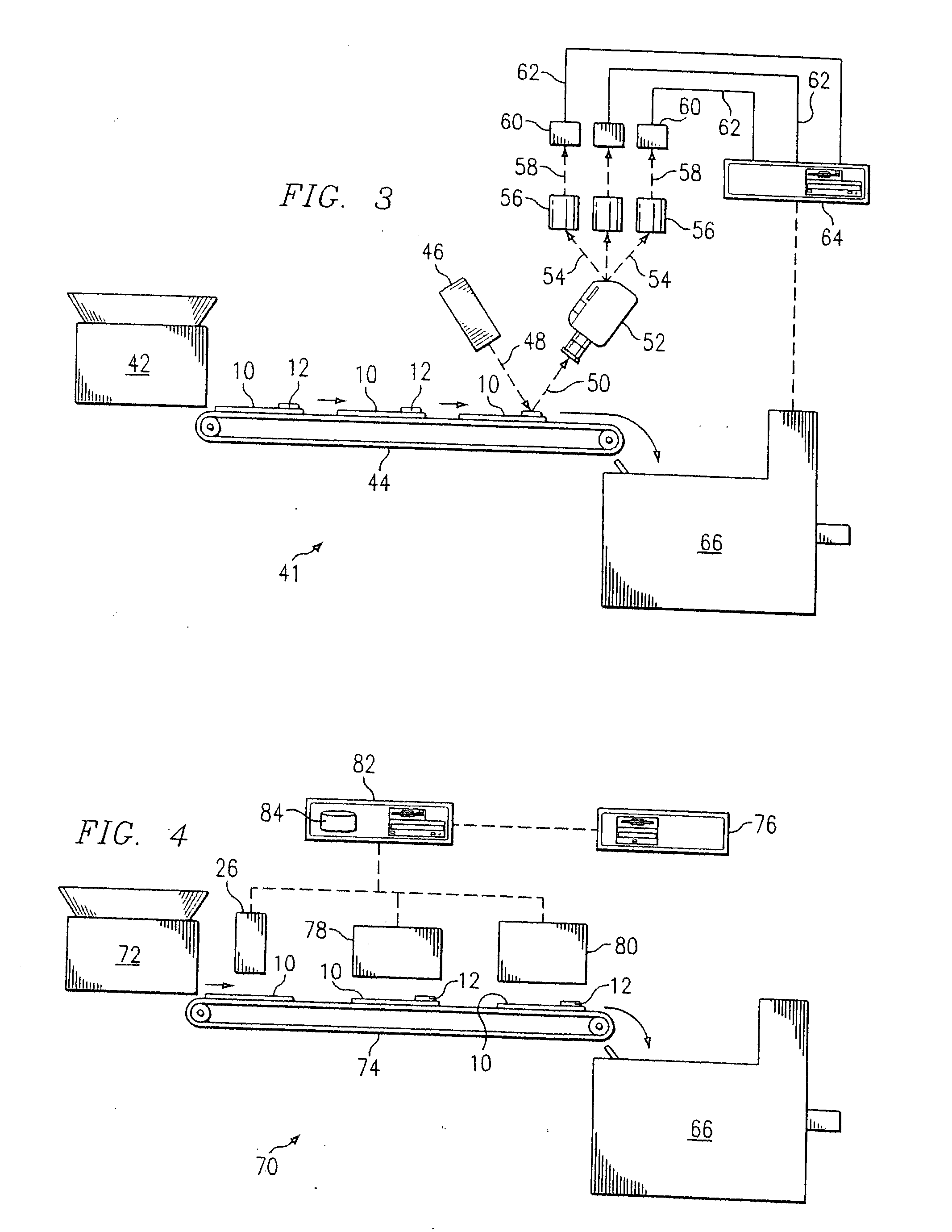
[0033] While the making and using of various embodiments of the present invention are discussed in detail below, it should be appreciated that the present invention provides many applicable inventive concepts which can be embodied in a wide variety of specific contexts. The specific embodiments discussed herein are merely illustrative of specific ways to make and use the invention and do not delimit the scope of the invention. In particular, while the invention is described in the context of mail piece identification and processing, it will be appreciated that the method and system described herein may be utilized in numerous other applications where it is desired to label items for the purposed of identification with minimal impact on the appearance of the article.

[0034] Sunlight and most forms of artificial light are electromagnetic waves whose electric field vectors vibrate in all perpendicular planes containing or orthogonal to the vector which indicates the direction of propag...


PUM


Abstract

A method of forming symbols, characters, and other images from a light polarizing material including machine readable indicia enabling automated identification of articles is disclosed. A light polarizing material is applied over a reflective layer in a machine readable pattern. The material may be an image imprinted on a label with a light polarizing material on a substrate such as a transparent oriented film. In one aspect, a mail processing system includes a computer including a database of destination codes corresponding to a plurality of mail pieces for delivery to at least some of the destination codes. A media applicator utilizes the database for generating and applying a light polarizing material to a label or article to form a machine readable indicia, including the destination code for each of the plurality of mail pieces. A mail sorting system utilizing the label includes a camera with polarized lenses for filtering light reflected from indicia formed from a light polarizing material on the label. A detector associated with each of the lenses for detecting reflected light and generating a signal in response thereto. Signals from the detector are compared by a computer that produces an electronic image or pattern corresponding to the machine readable indicia and generates a sorting signal based upon the indicia which is transmitted to a mail sorter where the mail pieces are sorted.

Description

[0001] This application is a division of U.S. patent application Ser. No. 10 / 033,735, filed Dec. 20, 2001 which claims priority based on U.S. Provisional Patent Application Ser. No. 60 / 258,986, filed Dec. 29, 2000.TECHNICAL FIELD [0002] The present invention relates to the field of article identification methods and systems, and particularly to a label, system and method that provides a means of coding articles for identification, sorting and processing with minimal visual impact. BACKGROUND OF THE INVENTION [0003] The system and method according to the invention may be advantageously applied in a variety of contexts where it is desired to label articles for identification with minimal impact on the appearance of the articles, for example items that have been specially wrapped for presentation, articles having critical information printed on an exterior surface, decorative items and the like. Another application in which the system and method of the invention may be advantageously u...

Claims


Application Information

Patent Timeline
Patent Type & Authority Applications(United States)
IPC IPC(8): G09F3/02
CPCG09F3/0297
Inventor MONDIE, GEORGE R.
Owner MONDIE GEORGE R
Why Eureka
Try Eureka