Web inspection and repair machine with retractable inspection zone

a technology of inspection zone and inspection machine, which is applied in the direction of manual label dispensers, lamination, cutting/splicing processed materials, etc., can solve the problems of reducing the work efficiency of the machine designer

Inactive Publication Date: 2007-08-16
PRITTIE FAMILY TRUST 1989
View PDF6 Cites 4 Cited by
  • Summary
  • Abstract
  • Description
  • Claims
  • Application Information

AI Technical Summary

Benefits of technology

[0026] (j) second control means adapted, upon detection of a flaw at the inspection zone, and upon braking of the web to a standstill, to move said support structure away from its essentially juxtaposed position with respect to the splicing area in such a fashion as to expose the splicing area for use by the operator to perform a repair, verification, or any type of modification, w

Problems solved by technology

If the error passes by the splice station it cannot be brought back to the splicing area because the machine is not capable of reversing the movement of the web.
While the web flow path in this machine design has been used in many thousands of machines, it suffers from drawbacks with respect to the manufacturing and processing demands of industry today.
Firstly, the industry is demanding that web inspection machines be capable of handling much larger unwind rolls.
Since, in the web flow path of the machine shown in FIG. 4 of U.S. Pat. No. 3,733,230, the web travels from the inspection zone around the unwind roll to reach the downstream fault splicing table at the left-hand side of the machine, making the unwind roll larger would force the machine designer to raise the inspection zone to an impractical height.
Secondly, the industry is also demanding that web inspection machines be capable of rewinding much larger rolls for later delivery in larger volumes to clients.
This need

Method used


Image

  • Web inspection and repair machine with retractable inspection zone
  • Web inspection and repair machine with retractable inspection zone
  • Web inspection and repair machine with retractable inspection zone

Examples


Embodiment Construction

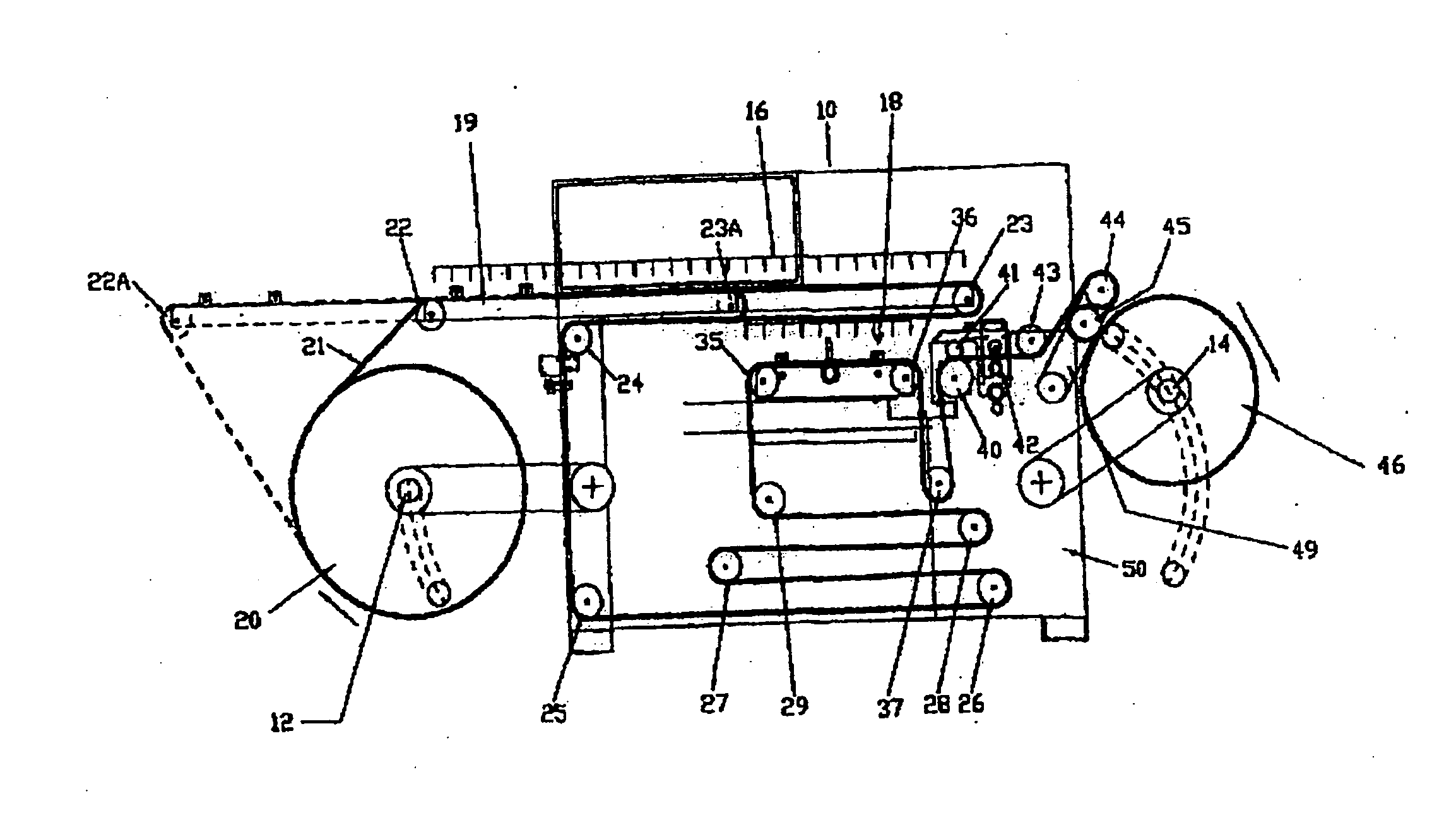
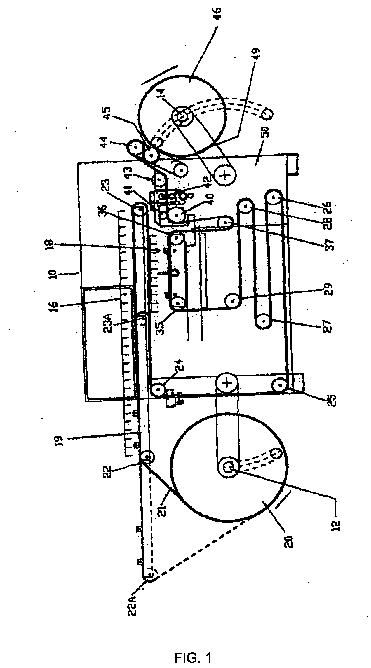
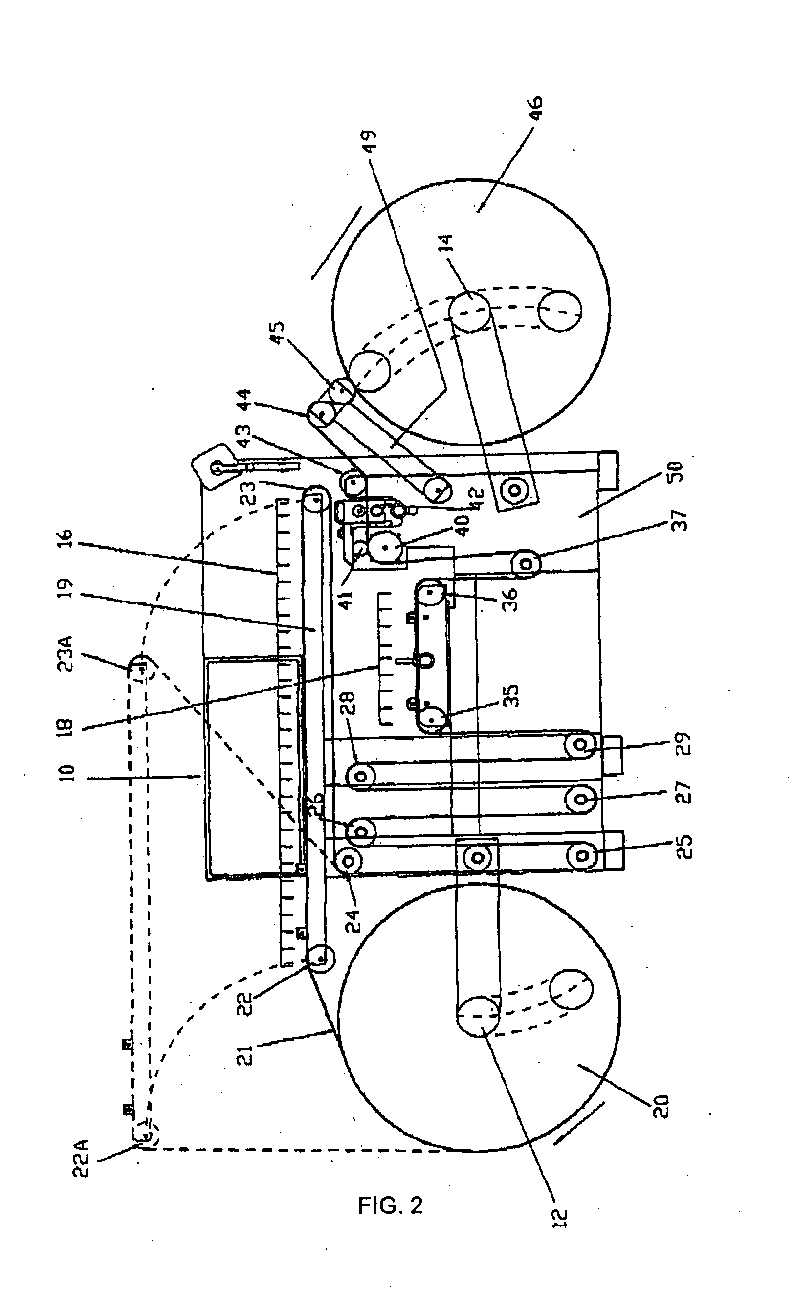
[0045] Attention is first directed to FIG. 1, which is a schematic side-elevational view showing the major components of a web processing mechanism to which the present invention has been applied.

[0046] The mechanism shown generally at 10 in FIG. 1 includes an unwind mandrel 12, a rewind mandrel 14, an inspection zone 16, and a splicing area 18.

[0047] A coil 20 of web material is mounted on the unwind mandrel 12, with the web 21 being paid off the coil 20. The web 21 is next threaded sequentially around rollers 22 and 23. The inspection zone 16 extends generally between rollers 22 and 23. Rollers 22 and 23 are mounted into an inspection zone support structure 19, which is movable between a first forward position (solid outline; FIG. 3) and a second rearward “retracted” position (dotted outline; FIG. 4).

[0048] The web 21 exiting the inspection zone support structure is sequentially entrained around fixed idler rolls 24, 25, 26, 27, 28 and 29. Web 21 is then entrained around idler ...


PUM

PropertyMeasurementUnit
Areaaaaaaaaaaa

Abstract

A web processing machine permitting inspection and repair of a roll of web material includes an inspection zone vertically juxtaposed to a splicing zone. The inspection zone is structured to be removed from the juxtaposed position to a retracted position in which the splicing zone is exposed to permit an operator to perform a modification of the web without having to substantially move physically from the position in which the operator was located to perform inspection while the machine is running.

Description

FIELD OF INVENTION [0001] This invention relates generally to web inspection and converting machines which are adapted to perform various process steps on an elongate web. The machine typically has an unwind mandrel and a rewind mandrel, and the web, which is provided initially in the form of a coil or roll of web material which can be fitted on the unwind mandrel. The web is then strung through various possible combinations of devices, such as idler rolls, error detectors, splicers, die cutters, print heads, web slitters and sheeters. Slitting the web may be required for a sequence of images, with two or more images located across the web. Inspection of the moving web can be done electronically or visually with the assistance of a stroboscope, or vision or video system that samples the moving web. BACKGROUND TO THE INVENTION [0002] In conventional web inspection machines, regardless of the means of error detection, the fundamental requirement is to locate the position of an error a...

Claims


Application Information

Patent Timeline
IPC IPC(8): B31F5/00G03D15/04
CPCB65H16/06Y10T156/12B65H18/145B65H20/24B65H21/00B65H26/02B65H2301/4148B65H2402/31B65H2407/22B65H2601/31B65H2601/325D06H3/00G03D15/04Y10T156/1087B65H16/106
Inventor PRITTIE, ALLAN R.
Owner PRITTIE FAMILY TRUST 1989
Why Eureka
Try Eureka