Vertically adjustable pipe support apparatus

a support apparatus and vertical adjustment technology, applied in the direction of mechanical equipment, machine supports, other domestic objects, etc., can solve the problems of the cost of installing the pipe system, unnecessary and awkward projection of the upper portion, and increasing the number of procedures. , to achieve the effect of increasing the safety of persons and being convenient to install

Inactive Publication Date: 2007-08-16
WORLD IND INC
View PDF4 Cites 37 Cited by
  • Summary
  • Abstract
  • Description
  • Claims
  • Application Information

AI Technical Summary

Benefits of technology

[0015] A pipe support apparatus according to the present invention avoids the need to have members projecting above the top of a pipe being supported, so the apparatus is easier to install than existing pipe support apparatuses because it does not require projecting portions to be cut off and covered with protective caps. The lack of projecting members also

Problems solved by technology

These projecting upper portions are unnecessary and awkward, especially when the pipe support apparatus is used under a floor.
These unnecessary projections may not only be obstacles to the movement of the inspection personnel but may also endanger them in that the projecting ends of the support pillars may hit or

Method used


Image

  • Vertically adjustable pipe support apparatus
  • Vertically adjustable pipe support apparatus
  • Vertically adjustable pipe support apparatus

Examples


Embodiment Construction

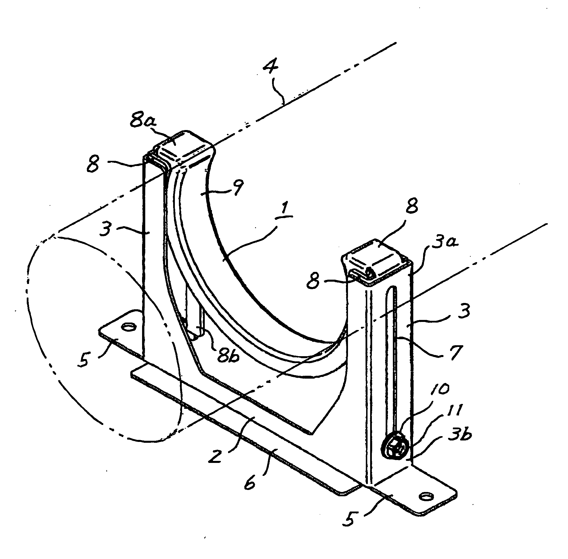
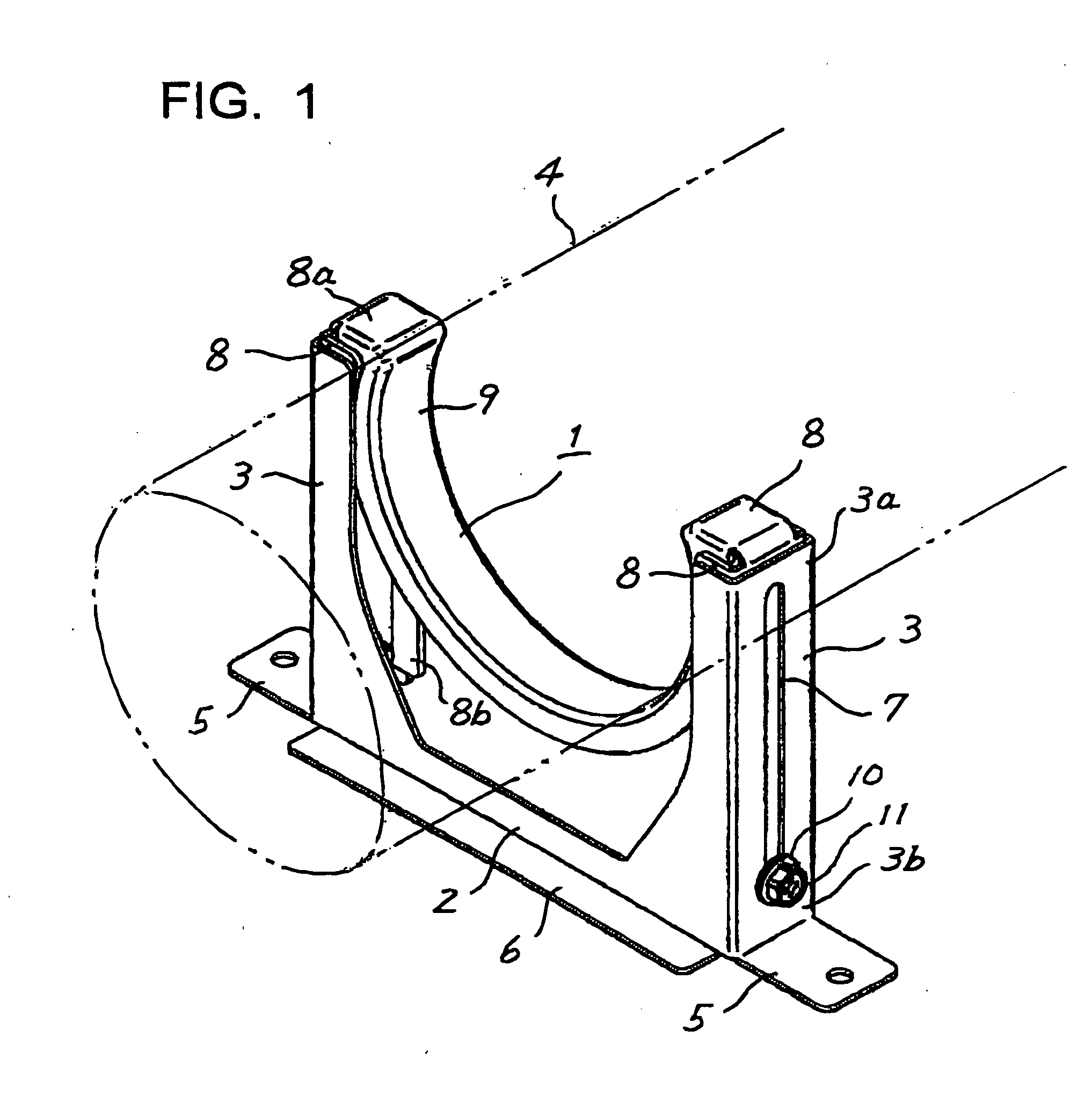
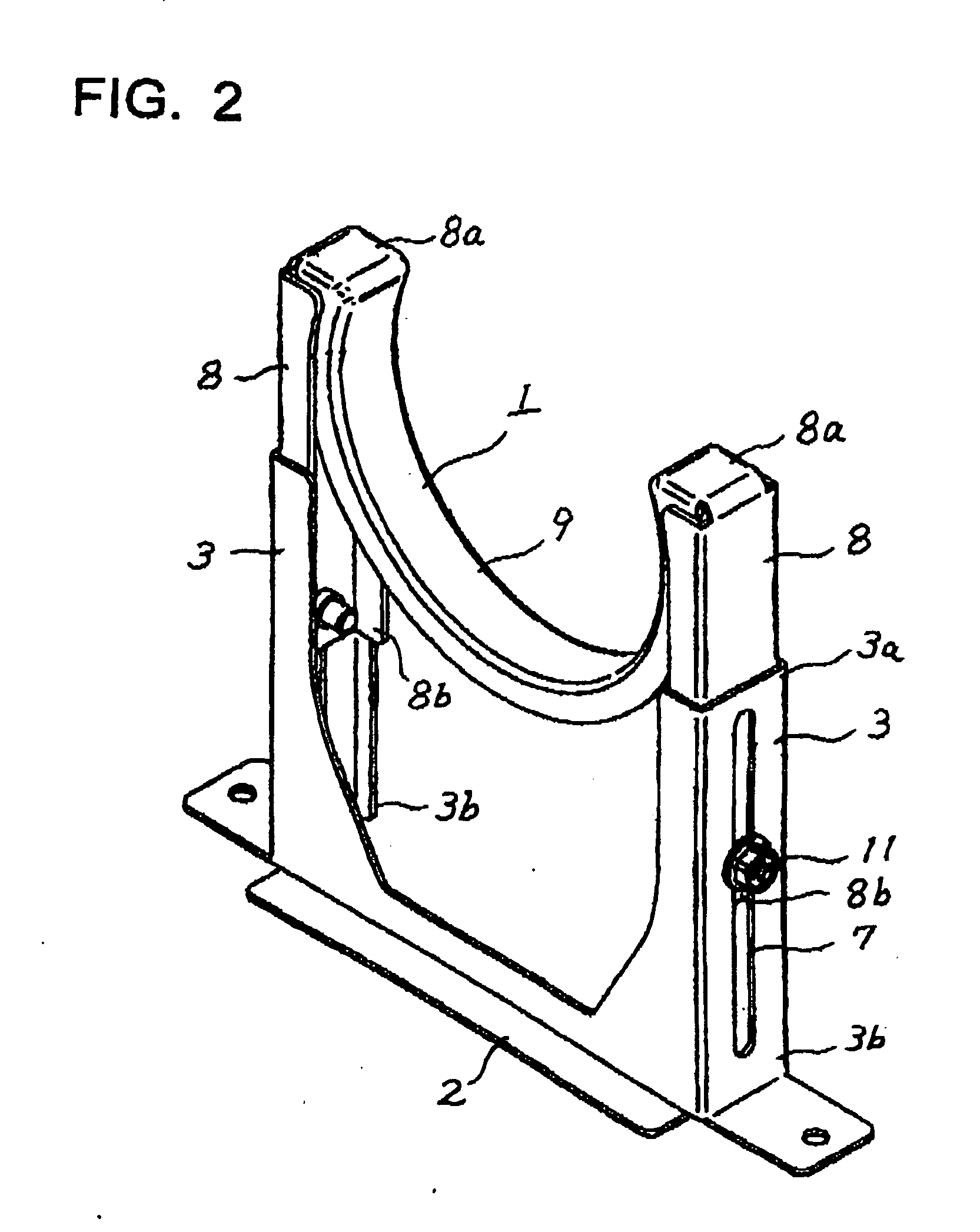
[0020] FIGS. 1 to 3 illustrate an embodiment of a pipe support apparatus 1 of the present invention, which comprises a base 2 and a first and second support pillar 3 mounted in parallel to each other on the base 2 and separated from each other by a distance larger than the diameter D of a pipe 4 to be supported. The base 2 and the two support pillars 3 in this embodiment are manufactured from a substantially U-shaped single piece of sheet metal so that they are integrally formed with each other. Each of the two legs of the U-shaped piece of sheet metal is bent along its length to form one of the support pillars 3, each of which has a substantially U-shaped cross section, a top end 3a, and a bottom end 3b. The leg portions of the support pillars 3 have outwardly extending tabs 5 at their bottom ends 3b. The bight portion of the U of the piece of sheet metal is bent at its bottom edge to form an outwardly extending flange 6 which, together with the tabs 5, forms the base 2. Each suppo...


PUM


Abstract

A vertically adjustable pipe support apparatus includes a pair of parallel support pillars supporting a pair of movable pillars for slidable movement along the support pillars to enable the movable pillars to be extended and retracted with respect to the support pillars. Each movable pillar can be releasably locked by a locking mechanism on the support pillars at a desired height along the support pillars. A pipe holder for supporting a pipe is connected between the top ends of the movable pillars. Each support pillar preferably has a length not exceeding the height of the top of a supported pipe when the movable pillars are in their fully retracted positions. Each movable pillar may have a length substantially equal to the length of the support pillars. The base and support pillars may be integrally formed with each other from a single piece of sheet metal, and the movable pillars and the pipe holder may be integrally formed with each other from another single piece of sheet metal.

Description

REFERENCE TO RELATED APPLICATIONS [0001] This application incorporates by reference the disclosure of Japanese Patent Application No. 2005-366322, filed on Dec. 20, 2005. BACKGROUND OF THE INVENTION [0002] This invention relates to a pipe support apparatus and particularly to a vertically adjustable pipe support apparatus for use in supporting a pipe system under the floor of a building. [0003] A conventional pipe support apparatus is arranged for supporting a pipe at an adjusted elevation and inclination so that a liquid in the pipe can smoothly flow through the supported pipe system. Japanese Patent Application Laid-Open No. 2004-204967 discloses one example of such a pipe support apparatus, which comprises a pair of parallel support pillars erected on a base and a pipe holder attached to the support pillars at a selected elevation. Each support pillar has a series of teeth along the pillar so that the pipe holder can be moved along the teeth and engaged at any selected position a...

Claims


Application Information

Patent Timeline
IPC IPC(8): E21F17/02
CPCF16L3/02F16L3/10F16L3/16
Inventor YOSHITAKE, NAOYUKI
Owner WORLD IND INC
Why Eureka
Try Eureka