Eyepiece lens group of a riflescope system

a riflescope system and lens group technology, applied in the field of eyepiece lens group of a riflescope system, can solve the problems of chromatic aberration, more difficult to correct aberration satisfactorily, difficult to correct with a reduced number of lens elements or with plastic lenses, etc., and achieve the effect of reducing the weight of the riflescope system and the total number of lenses in the riflescope system

Inactive Publication Date: 2007-08-16
ASIA OPTICAL CO INC
View PDF4 Cites 1 Cited by
  • Summary
  • Abstract
  • Description
  • Claims
  • Application Information

AI Technical Summary

Benefits of technology

[0009] A main object of the present invention is to provide an eyepiece lens group of a riflescope system employing a plastic optical lens having aspherical and aiffractive surfaces such that the total numbers of lenses in the riflescope system could be reduced and the weight of the riflescope system could be reduced.

Problems solved by technology

However, the reduction of the number of lens elements and the use of plastic lenses make it more difficult to correct aberration satisfactorily.
In particular, chromatic aberration, which can be corrected only with a combination of lenses made of materials having different dispersion, is difficult to correct with a reduced number of lens elements or with plastic lenses.
In addition, since there are only few kinds of plastic that can be used satisfactorily as lenses, it is not possible to freely select plastic materials having different dispersions for the correction of chromatic aberration.
Accordingly, it is difficult to use plastic lenses for all the lens elements constituting an optical system.
Furthermore, there is deterioration in the image-formation performance of a typical riflescope system due to the environmental conditions such as temperature and / or humidity.
The conventional riflescope system utilizes cemented lenses in order to abate chromatic aberration, however, this process increases the weight and cost of such riflescope system.

Method used


Image

  • Eyepiece lens group of a riflescope system
  • Eyepiece lens group of a riflescope system
  • Eyepiece lens group of a riflescope system

Examples


Embodiment Construction

[0016] In the following detailed description of the present invention, numerous specific details are set forth in order to provide a thorough understanding of the present invention. However, it will be obvious to one skilled in the art that the present invention may be practiced without these specific details. In other instances well known methods, procedures, components, and circuits have not been described in detail so as not to unnecessarily obscure aspects of the present invention.

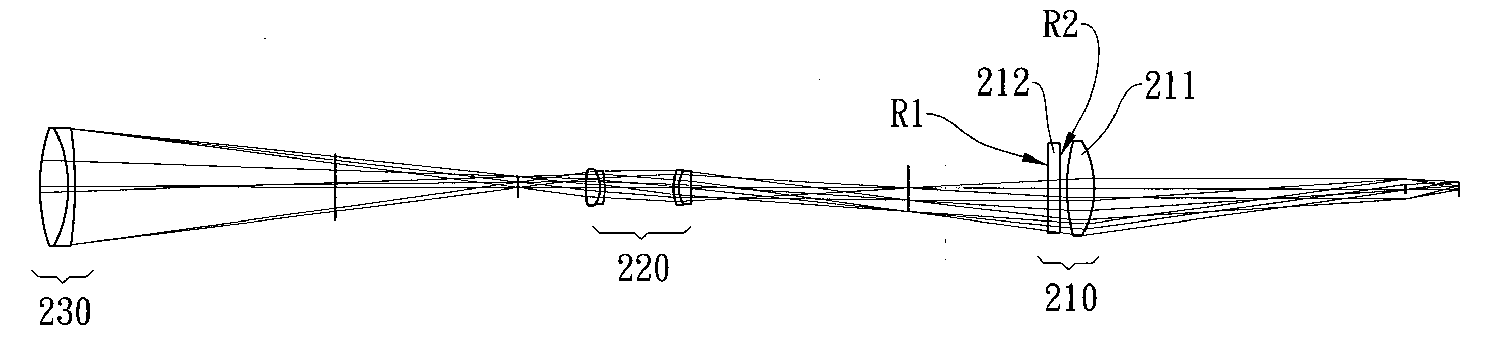
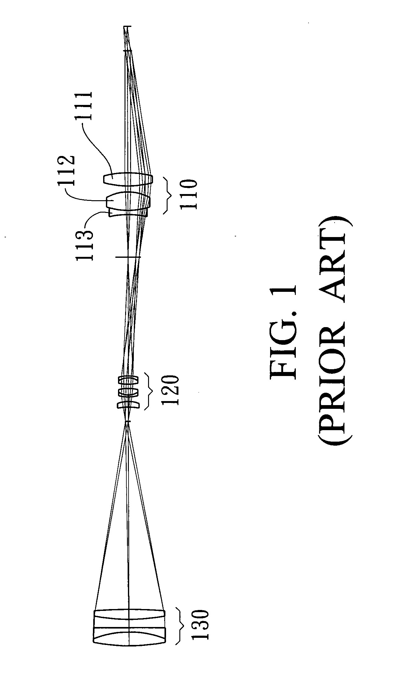
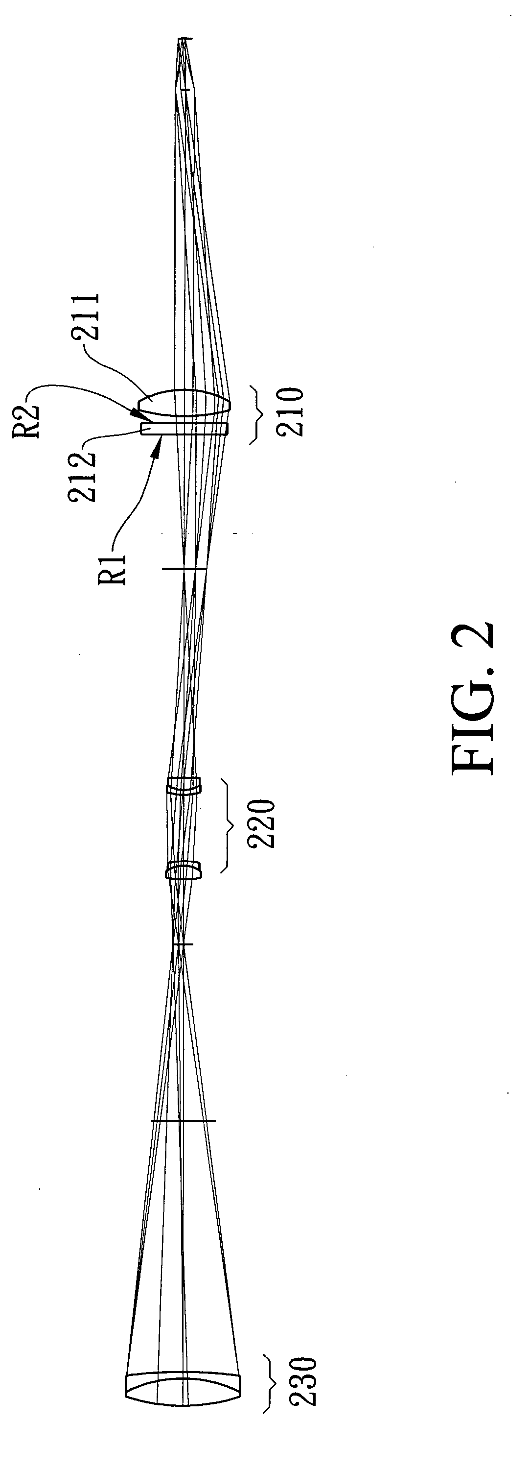
[0017] Referring to FIG. 2 of the drawings, a cross-sectional view and optical paths of a viewfinder optical system according to a preferred embodiment of the present invention is illustrated, in which the viewfinder optical system comprises three lens groups, an eyepiece lens group 210, an erector lens group 220, and an objective lens group 230. The conventional eyepiece lens group 110 which has three glass lenses, a convexo-convex lens 111, a convexo-convex lens 112, and a concavo-concave lens 113, ...


PUM


Abstract

An eyepiece lens group in a riflescope system comprises, from a front, eye side to a rear, object side, a glass lens and a plastic lens. The plastic lens has an aspherical surface and a diffractive surface, wherein the diffractive surface is on the front surface of the plastic lens and the aspherical surface is on the rear surface of the plastic lens. The aspherical surface of the plastic lens is utilized to abate the aberration. The diffractive surface of the plastic lens is utilized to abate the chromatic aberration. Therefore, the total numbers of lenses of the eyepiece lens group in the riflescope system could be reduced and the weight of the riflescope system could be reduced.

Description

BACKGROUND OF THE PRESENT INVENTIONIN [0001] 1 . Field of Invention [0002] The present invention relates to an eyepiece lens group of a riflescope system, and more particularly to an eyepiece lens group of ariflescope system utilizing a plastic lens having aspherical and diffractive surfaces instead of glass lens. [0003] 2 . Description of Related Arts [0004] Conventional riflescope systems are composed of a number of glass lenses, and these have prevented the reduction of the weight, size, and cost of such viewfinder optical systems. These inconveniences can be overcome by reducing the number of constituent lens elements. [0005] However, the reduction of the number of lens elements and the use of plastic lenses make it more difficult to correct aberration satisfactorily. In particular, chromatic aberration, which can be corrected only with a combination of lenses made of materials having different dispersion, is difficult to correct with a reduced number of lens elements or with pl...

Claims


Application Information

Patent Timeline
Patent Type & Authority Applications(United States)
IPC IPC(8): G02B27/64
CPCF41G1/38G02B27/4211G02B27/0037G02B23/14
Inventor LIAO, CHEN-CHENLIANG, SHANG-YUNG
Owner ASIA OPTICAL CO INC
Why Eureka
Try Eureka