Cage for inclined ball bearings

Active Publication Date: 2007-08-16
SCHAEFFLER TECH AG & CO KG
View PDF6 Cites 3 Cited by
  • Summary
  • Abstract
  • Description
  • Claims
  • Application Information

AI Technical Summary

Benefits of technology

[0007] It is therefore the object of the invention to provide a cage which meets the above-mentioned and partially

Problems solved by technology

The thin-walled configuration is subject to limitations as a result of the requirements for high operating strength of the cage.
Otherwise, thin-walled plastic parts are extremely unstable after removal from the die and

Method used


Image

  • Cage for inclined ball bearings
  • Cage for inclined ball bearings
  • Cage for inclined ball bearings

Examples


Example

DETAILED DESCRIPTION OF THE DRAWINGS

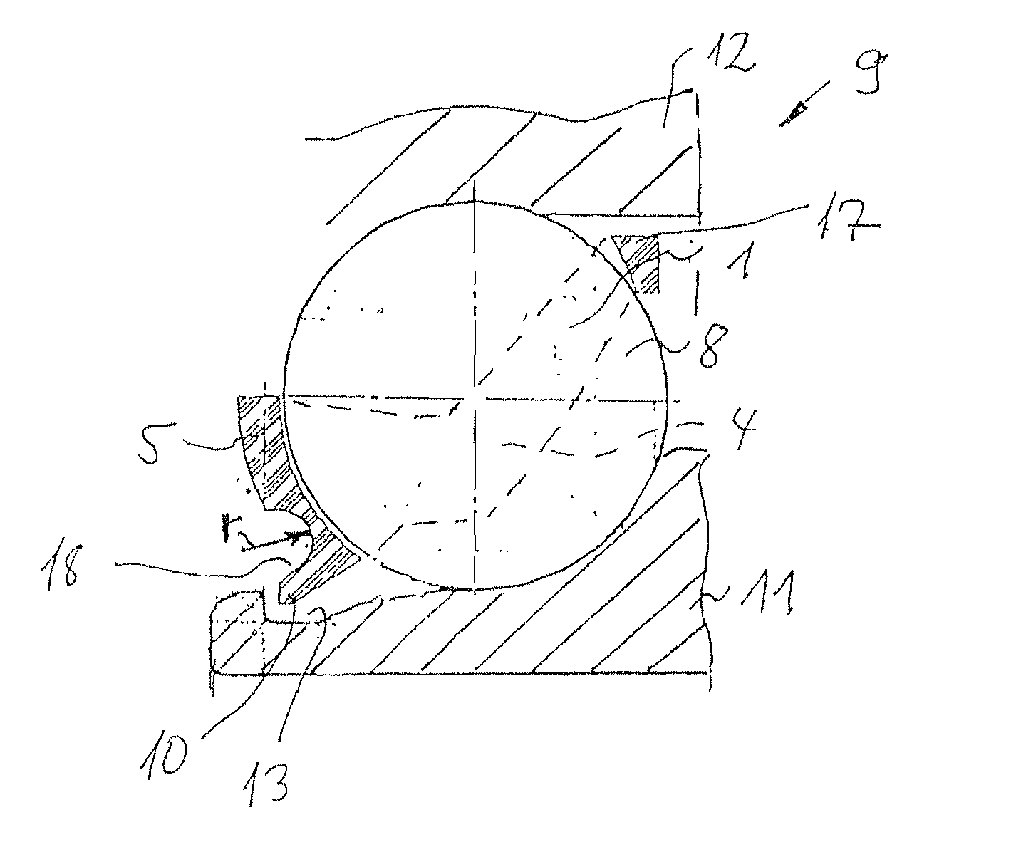
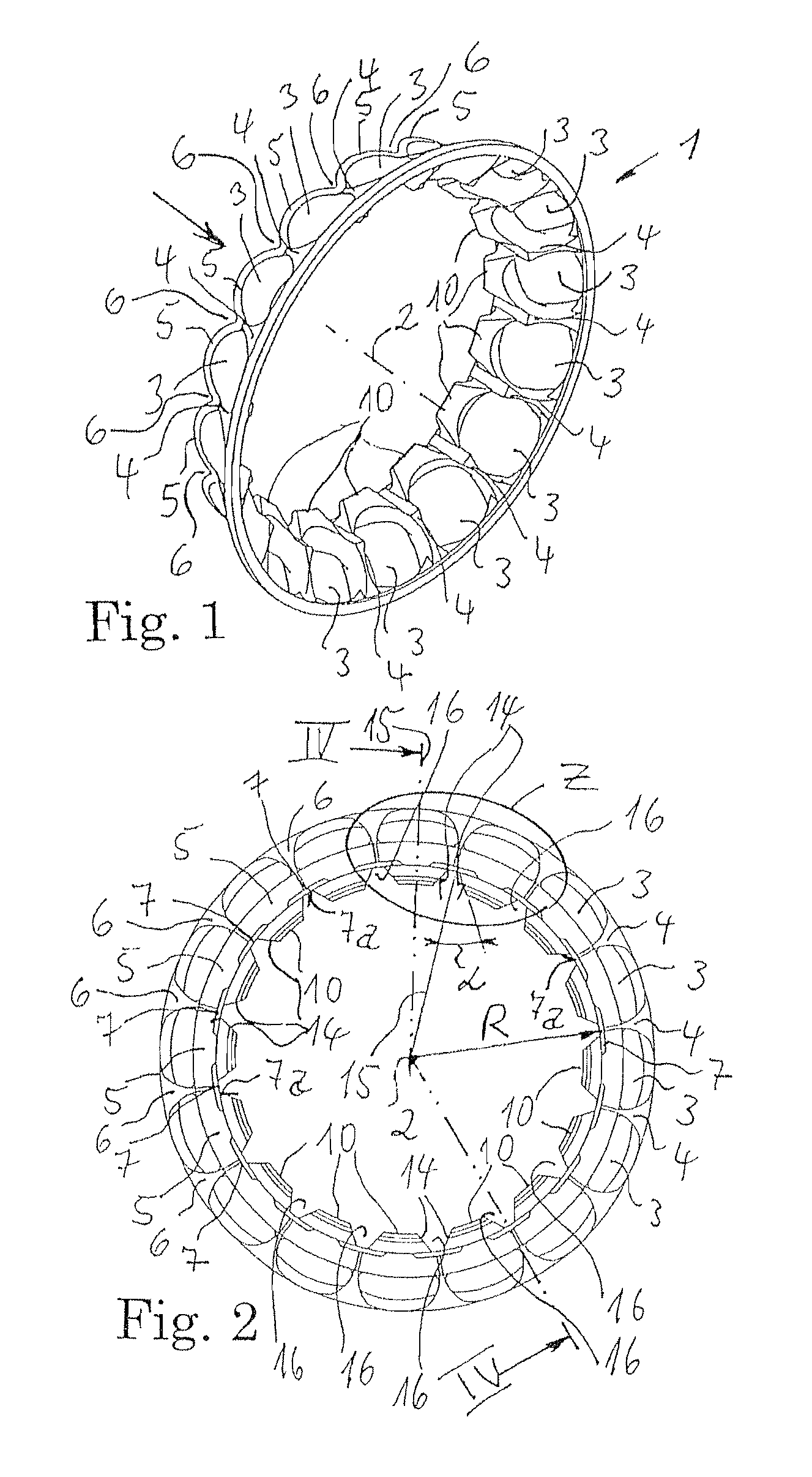
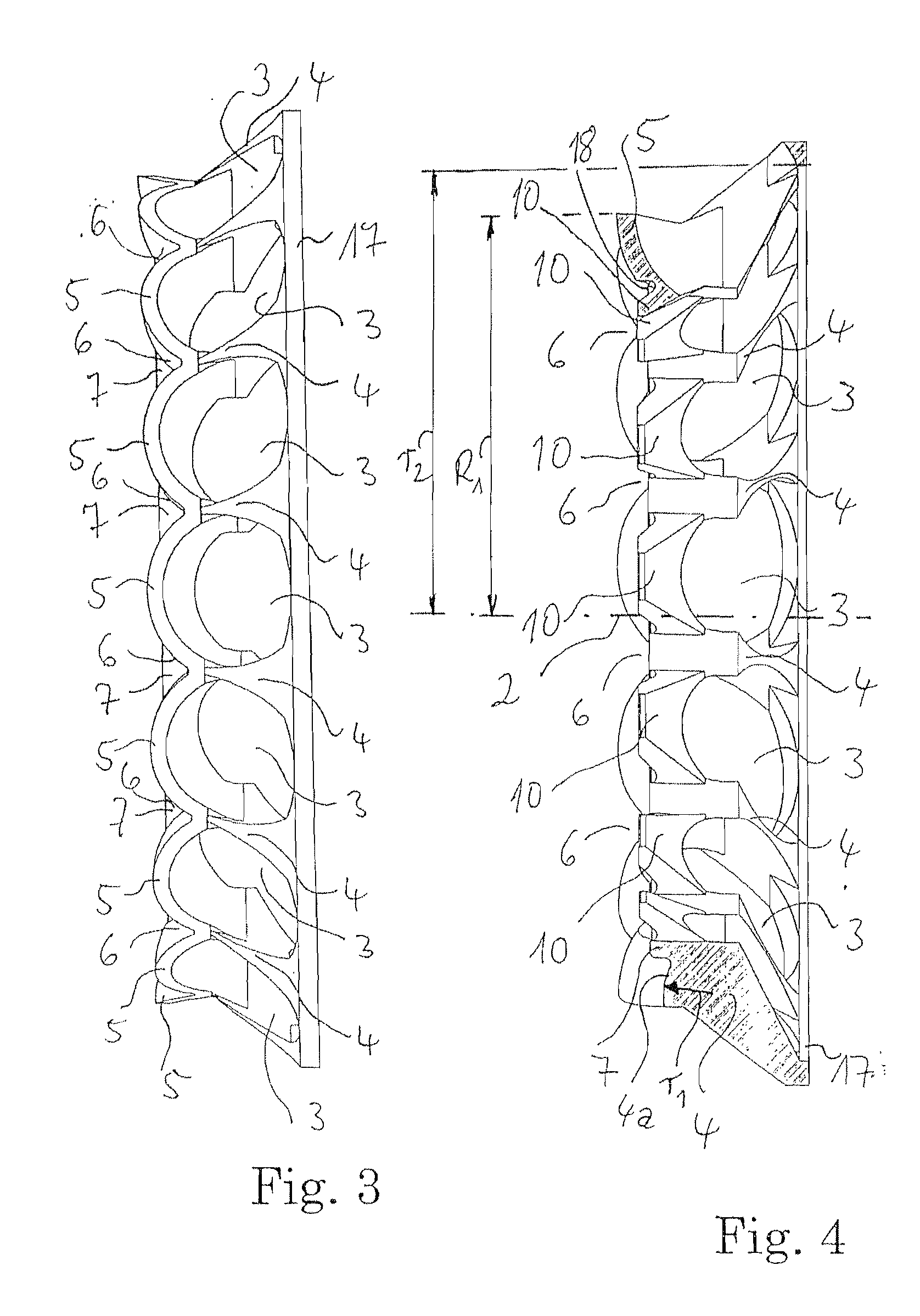
[0025] FIGS. 1 to 3 show an exemplary embodiment of a cage 1 according to the invention. The cage has ball pockets 3 which are adjacent on the circumferential side about its rotational axis 2 with respect to one another with a uniform pitch. A ball 8 is guided in each individual ball pocket 3. FIG. 5, a sectional partial view of an inclined ball bearing 9, shows the cage 1 which is arranged radially between an inner ring 11 and an outer ring 12 with balls 8. The ball pockets 3 are delimited by webs 4 which extend transversely with respect to the circumferential direction. On one end side, the cage 1 is delimited by side walls 5 having an approximately uniform wall thickness.

[0026] The side walls 5 are arched from the webs 4 in the axial direction, with the result that axial gaps 6 are formed on the end side of the cage 1. The gaps 6 are delimited in the radial direction of the rotational axis 2 by in each case one rib 7. The ribs 7 are oriented ...


PUM


Abstract

The invention relates to a cage for inclined ball bearings with adjacent ball pockets arranged on the circumferential side around a rotational axis of the cage, comprising ribs between lateral walls. Each rib extends in the axial direction from one of the lands and connects two of the lateral walls together on the circumferential side.

Description

FIELD OF THE INVENTION [0001] The present invention relates to a cage for inclined ball bearings having ball pockets which are adjacent to one another on the circumferential side about a rotational axis of the cage, the ball pockets being delimited on the circumferential side by webs and, in at least one axial direction of the cage, in each case by a side wall having an approximately uniform wall thickness. BACKGROUND OF THE INVENTION [0002] A cage of this type is described in DE 3706013 A1. The cage has two side rings which are connected to one another by webs. One of the side rings is arranged on one side of the cage above the pitch circle and another of the side rings is arranged below the pitch circle. The side rings of the cage are provided with annular grooves, starting from the end sides. Cages of this type are manufactured from plastic. Typical examples of materials which are used for the manufacture of cages of this type are polyamides which are reinforced with glass or wit...

Claims


Application Information

Patent Timeline
IPC IPC(8): F16C33/44F16C19/16F16C33/38
CPCF16C19/14F16C33/3856F16C33/3806F16C19/163
Inventor HAEPP, ALEXANDER
Owner SCHAEFFLER TECH AG & CO KG
Why Eureka
Try Eureka