
Fixing apparatus and image forming apparatus

Inactive Publication Date: 2007-08-16
SHARP KK
View PDF11 Cites 24 Cited by
  • Summary
  • Abstract
  • Description
  • Claims
  • Application Information

AI Technical Summary

Benefits of technology

[0012] In view of the foregoing problems, the present invention was devised. An object of the present invention is to provide (i) an external belt heat type fixing apparatus

Problems solved by technology

However, in the fixing roller having the elastic layer, the elastic layer cannot sufficiently conducts heat.
Thus, in case where the heating means is provided in the fixing roller, heat is less efficiently conducted, so that it takes longer time to warm up.
However, in case where one of the belt suspending rollers is used as a tension roller, this requires a complicate mechanism for exerting a tension to the endless belt.
Further, it is impossible to keep the plural belt suspending rollers in parallel to each other, so th

Method used


Image

  • Fixing apparatus and image forming apparatus
  • Fixing apparatus and image forming apparatus
  • Fixing apparatus and image forming apparatus

Examples


Example

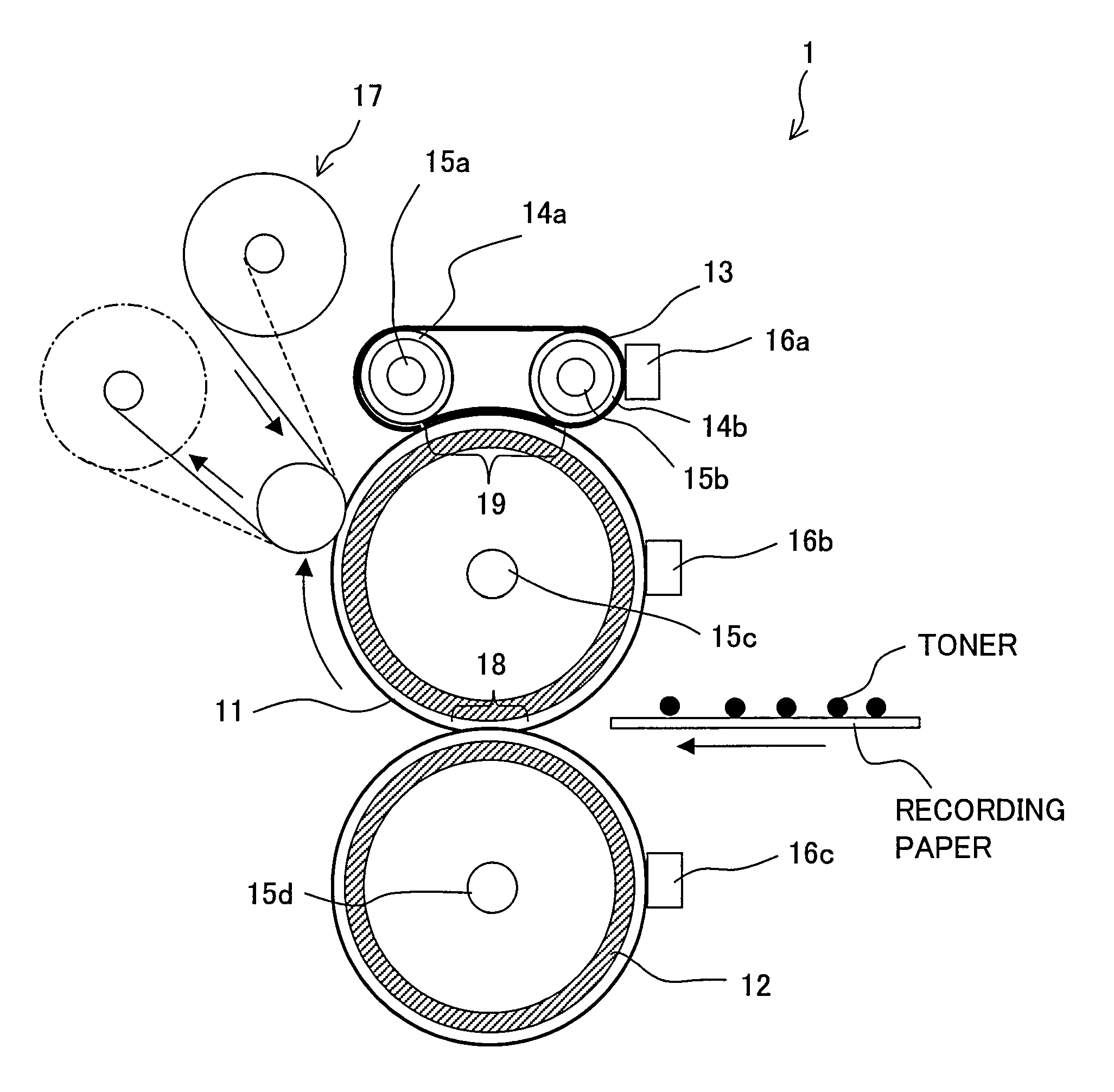
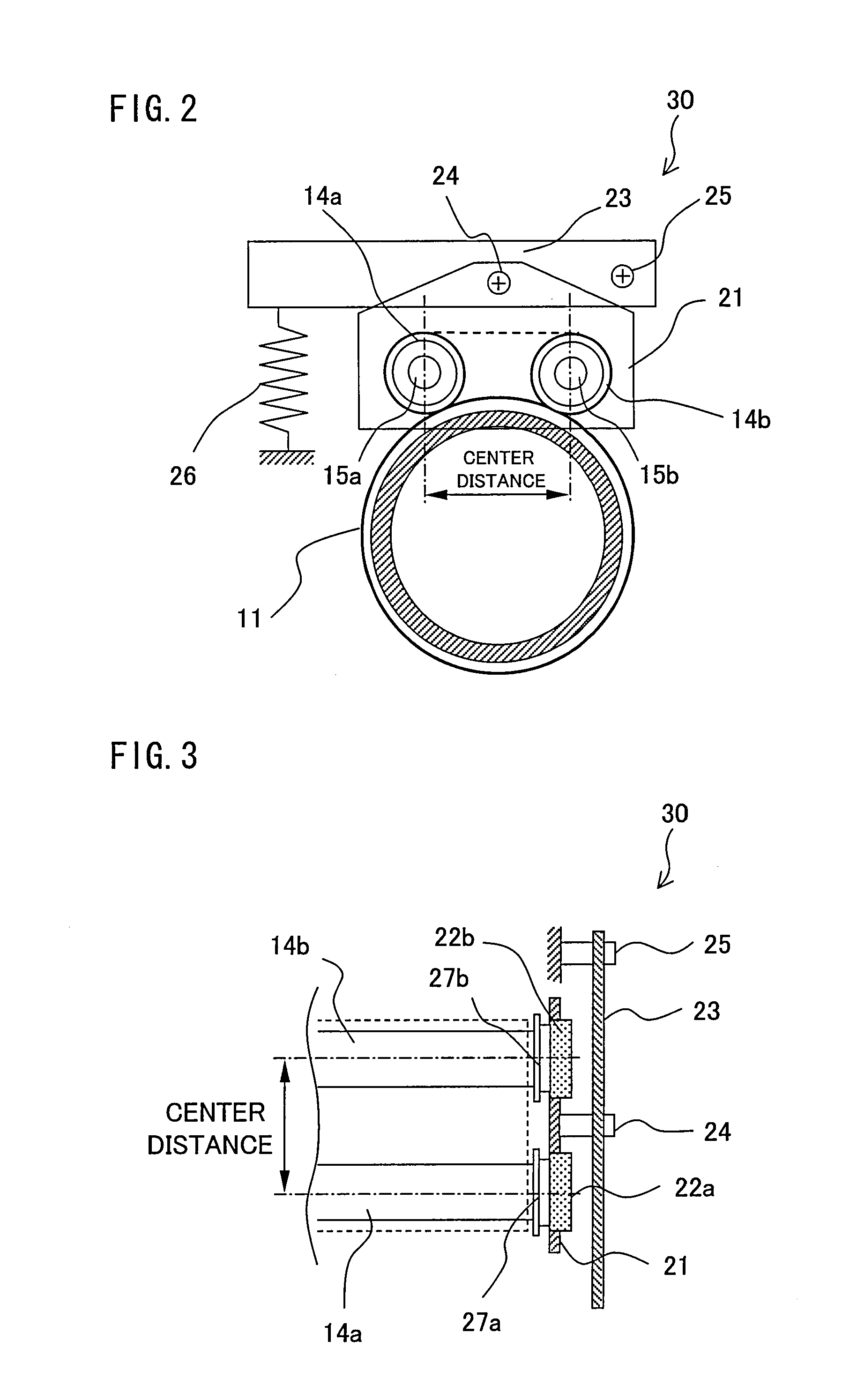
[0095] The deviation speed of Comparative Example 1 was the highest for the following reason: the tension is exerted to the external heating belt 13 by externally pushing the heating roller 14a, so that it is impossible to secure the parallelism between the heating rollers 14a and 14b. Further, in Comparative Example 2, the parallelism between the heating rollers 14a and 14b is the same as in the present example, but it is impossible to secure the parallelism between (i) the heating rollers 14a and 14b and (ii) the tension roller 102, so that the deviation speed is higher than in the present example.

[0096] As a result of the durability test, breakage occurred in the belt end at an earliest timing in Comparative example 1 (30 hours later), and breakage occurred 160 hours later in Comparative Example 2, and no breakage occurred even 200 hours later in the present example. These results substantially correspond to results of the test concerning the belt deviation speed.

[0097] As to t...


PUM


Abstract

A center distance between heating rollers for suspending an external heating belt is fixed, and a peripheral length of the external heating belt is set so that a tension is not exerted to the external heating belt when the external heating belt is not pressed against the fixing roller and the tension is exerted to the external heating belt when the external heating belt is pressed against the fixing roller. As a result, it is possible to provide an external belt heating type fixing apparatus, having a simple arrangement, which is excellent in a thermal efficiency and can suppress snaking of the belt.

Description

[0001] This Nonprovisional application claims priority under 35 U.S.C. § 119(a) on Patent Application No. 34454 / 2006 filed in Japan on Feb. 10, 2006, the entire contents of which are hereby incorporated by reference. FIELD OF THE INVENTION [0002] The present invention relates to (i) an external belt heating type fixing apparatus used in an electrophotographic image forming apparatus and (ii) an image forming apparatus having the fixing apparatus. BACKGROUND OF THE INVENTION [0003] As a fixing apparatus used in an electrophotographic image forming apparatus such as a copying machine, a printer, and the like, a heat roller type fixing apparatus is frequently used. The heat roller type fixing apparatus includes a pair of rollers (a fixing roller and a pressing roller) which are pressed against each other, wherein heating means constituted of halogen heaters disposed in both the rollers or a halogen heater disposed in one of the rollers heats the pair of rollers at a predetermined tempe...

Claims


Application Information

Patent Timeline
IPC IPC(8): G03G15/20
CPCG03G15/2064G03G2215/00143G03G2215/00151G03G2215/2019G03G2215/2016
Inventor KAGAWA, TOSHIAKI
Owner SHARP KK
Learn More