Multifunctional portable multi-rotor unmanned aerial vehicle

A multi-rotor unmanned aerial vehicle, portable technology, applied in the field of multi-functional portable multi-rotor unmanned aerial vehicle, can solve the problems of difficulty in judging the flight and flight direction of the aircraft, difficulty in meeting customer requirements, inconvenient packaging and transportation, etc., to shorten the preparation time. , The effect of saving preparation time and transportation space, and reducing the volume of transportation packaging

Active Publication Date: 2018-02-02
HUNAN SUNWARD SCI & TECH
View PDF6 Cites 9 Cited by
  • Summary
  • Abstract
  • Description
  • Claims
  • Application Information

AI Technical Summary

Problems solved by technology

[0003] In the fuselage structure of a multi-rotor unmanned aerial vehicle, the arms are usually folded in the vertical direction, and the space occupied after folding is still a bit large, which brings inconvenience to packaging and transportation
At present, most of the multi-rotor aerial photography UAVs on the market are of fixed layout structure, which is inconvenient to disassemble and assemble different loads, and has a single function, which makes it difficult to meet the requirements of the same customer in different periods, different occasions, and different purposes. At the same time, if the aircraft is flying in the air, if there is no navigation light and warning light, it is difficult to judge the flight direction of the aircraft with the naked eye, which may easily lead to accidents

Method used


Image

  • Multifunctional portable multi-rotor unmanned aerial vehicle
  • Multifunctional portable multi-rotor unmanned aerial vehicle
  • Multifunctional portable multi-rotor unmanned aerial vehicle

Examples


Embodiment

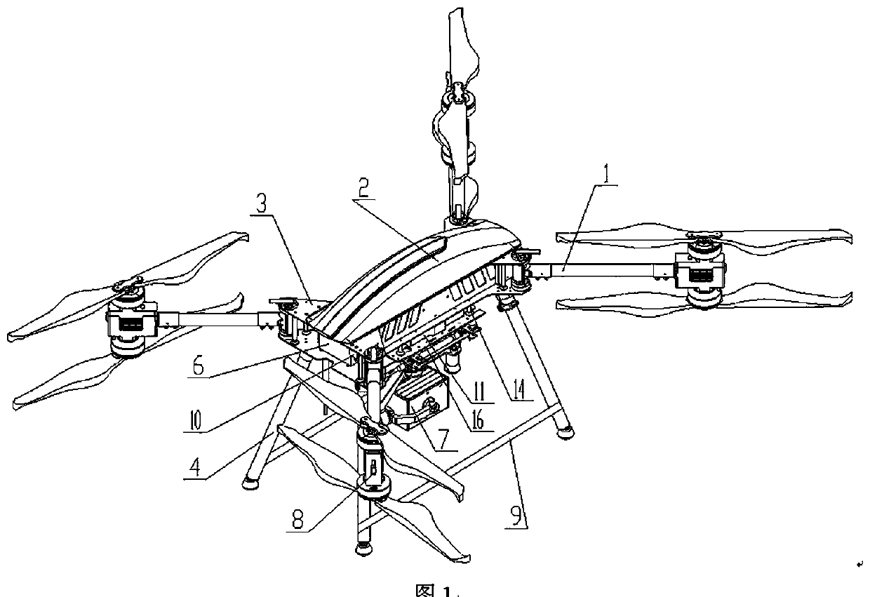
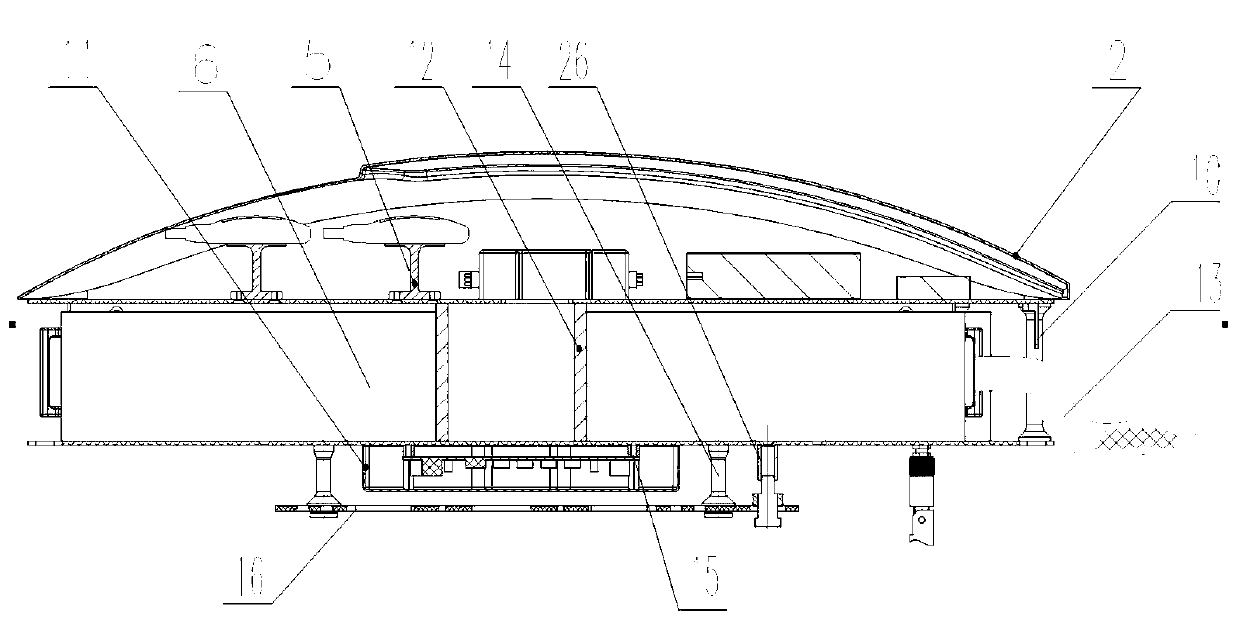
[0057] see Figure 1~Figure 2 , the present embodiment provides a multifunctional portable multi-rotor UAV, including a rotor assembly 1, a frame 3, a tripod 4, a rain cover 2, a control system 5, a battery 6, and a task load 7. The frame 3 is divided into four layers, the first layer is installed with control system 5, the second layer is installed with battery 6, the third layer is installed with image transmission equipment, and the bottom layer 4 is equipped with different task loads through quick change devices, which can be mounted Variable focal length visible light camera, infrared camera, laser radar, megaphone, throwing device and other loads.

[0058] The rainproof cover 2 is installed on the top of the frame 3, covers the control system 5, and has a certain rainproof effect on the equipment on the upper and lower floors. The rotor assembly 1 can be folded horizontally, and after the tripod 4 is removed, the aircraft can be directly packed into a backpack and taken...


PUM


Abstract

The invention belongs to the technical field of unmanned aerial vehicles, and provides a multifunctional portable multi-rotor unmanned aerial vehicle. The multifunctional portable multi-rotor unmannedaerial vehicle includes a rack, a foot frame and at least four rotor assemblies. The rack includes an upper center plate and a lower center plate. The upper part of the upper center plate is providedwith a flight control mounting layer, and the flight control mounting layer is internally provided with a control system. A battery mounting layer is arranged between the upper center plate and the lower center plate, and the battery mounting layer is internally provided with a battery. The battery can be positioned and fixed quickly through a partition plate. The lower part of lower center plateis provided with a task load mounting layer. Load equipment and the lower center plate can be quickly connected and disassembled through a fast replacing device. The rotor assemblies are arranged onthe periphery of the rack and are connected with the rack through a fast horizontal folding device. The foot frame is arranged on the periphery of the rack, and the foot frame and the rack are fast connected and disassembled through a wedge-shaped pipe clamp. The multifunctional portable multi-rotor unmanned aerial vehicle is a multi-rotor remote control vehicle which can be folded, multi-layer arranged and is long in endurance, small in size, multifunctional, quick and convenient to assemble and disassemble, safe and modular and is an industrial unmanned aerial vehicle solution for being fastexpanded and being suitable for different operating conditions.

Description

technical field [0001] The invention belongs to the technical field of unmanned aerial vehicles, and more specifically relates to a multifunctional portable multi-rotor unmanned aerial vehicle. Background technique [0002] At present, in the field of UAVs, multi-rotor UAVs have the characteristics of flexible maneuverability, fast response, unmanned driving, and low operating requirements. UAVs are equipped with various types of sensors, such as cameras, which can realize real-time image transmission and detection of high-risk areas. Functions, widely used in firefighting, military, traffic, police, exploration and meteorology, etc., to achieve cruising shooting and monitoring of designated areas. [0003] In the fuselage structure of a multi-rotor unmanned aerial vehicle, the arms are usually folded in the vertical direction, and the space occupied after folding is still a bit large, which brings inconvenience to packaging and transportation. At present, most of the multi...

Claims


Application Information

Patent Timeline
Patent Type & Authority Applications(China)
IPC IPC(8): B64C27/10B64C1/30B64D45/00B64D27/24B64D27/26B64D47/00B64D47/06B64D47/08
CPCB64C1/30B64C27/10B64D27/24B64D27/26B64D45/00B64D47/00B64D47/06B64D47/08B64D2027/262B64U10/10B64U50/19
Inventor 邓宇雷传辉谢习华彭礼王辉
Owner HUNAN SUNWARD SCI & TECH
Why Eureka
Try Eureka