Triaxial type active transmission device of automobile

A transmission device and shaft-type technology, which is applied in the direction of power devices, pneumatic power devices, control devices, etc., can solve the problems of not being able to fully share the transmission path, etc., and achieve simple space layout and support methods for shaft systems, high transmission efficiency, and structural compact effect

Inactive Publication Date: 2012-01-04
TONGJI UNIV
View PDF9 Cites 10 Cited by
  • Summary
  • Abstract
  • Description
  • Claims
  • Application Information

AI Technical Summary

Problems solved by technology

Based on this principle, the power transmission path between the two independent intermediate shafts in the hybrid transmission is in a subordinate position, and its establishment and cancellation are realized indirectly based on the bridge gear set, which makes it impossible for the two prime movers to fully share their respective Transmission path belonging to the output shaft
The present invention intends to overcome the above limitations. (1) Firstly, instead of using the bridge gear set, it directly adopts the locking synchronous mechanism, which is intended to effectively improve the torque transmission efficiency and capacity between the motor shaft and the input shaft; (2) Secondly , the two prime movers share a set of transmission mechanism, and the motor switches to the second power transmission path for a short time during the gear shift; (3) In addition, the patent 03811785.1 focuses on the structure of the longitudinal gearbox, but it is not applicable to the implementation of the transverse front drive gearbox limitation

Method used


Image

  • Triaxial type active transmission device of automobile
  • Triaxial type active transmission device of automobile
  • Triaxial type active transmission device of automobile

Examples


Embodiment Construction

[0046] The present invention will be described in detail below in conjunction with the accompanying drawings.

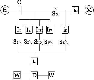
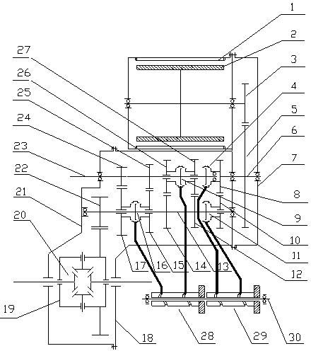
[0047] Such as figure 1 As shown, the present invention provides a three-axis active transmission device, its structure is as attached figure 2 As shown, it includes: motor stator 1, motor rotor 2, motor deceleration drive gear 3, motor shaft / input shaft synchronous locking mechanism 4, motor deceleration driven gear 5, motor shaft 6, right box body 7, motor output drive Gear 8, III / IV gear synchrolock mechanism 9, motor output driven gear 10, motor output synchrolock mechanism 11, IV gear driven gear 12, output shaft 13, III gear driven gear 14, II gear driven Gear 15, I / II gear synchronous locking mechanism 16, I gear driven gear 17, main case 18, differential assembly (integrated main speed driven gear) 19, output half shaft 20, left case 21 , main speed device driving gear 22, input shaft 23, I gear driving gear 24, II gear driving gear 25, III gear driving ge...


PUM


Abstract

The invention discloses a triaxial type active transmission device of an automobile. The device is characterized by comprising a motor shaft AM, wherein the motor shaft AM is in driving connection with a motor M through a fixed speed ratio IM; the motor shaft AM is coincident with a rotary central line of an input shaft AI and the locking connection of the motor shaft AM and the input shaft AI can be achieved through a locking synchronous mechanism SM; an unique torque transmission route (ID) and a corresponding locking synchronous mechanism (SD) are arranged between the motor shaft AM and an output shaft AO; the input shaft AI and the motor shaft AM can sufficiently share a respective variable speed route to the output shaft. The triaxial type active transmission device of the automobile has the functions of parking charging, charging in vehicle cruise driving, feedback braking, vehicle forwarding driven by the motor / engine commonly, pure power-driven traveling, vehicle forwarding driven by the engine independently, starting by virtue of the power of the motor and the like. In the invention, the shutting locking of the motor shaft AM and the input shaft AI can be realized. The device disclosed by the invention has the advantages of high transmission efficiency, compact structure, simple axial system space arrangement and supporting manner, convenience in arrangement of a plurality of gears and the like.

Description

technical field [0001] The invention relates to a transmission device, in particular to an automobile three-axis active transmission device. Background technique [0002] Among the main types of transmissions in the traditional automotive transmission technology field, fixed-axis manual transmission (MT) has high transmission efficiency, convenient manufacturing and processing, low cost and high reliability, so it has always been the mainstream technology in the domestic vehicle transmission market. However, MT has some problems in the operation and use of the vehicle, especially in special driving conditions such as starting on a slope. Compared with other types of transmissions, it is inconvenient to operate; in addition, poor timing of shifting will increase fuel consumption and engine wear. The operator's operation burden is heavy. In the known art it is proposed to use an automatically operated shift mechanism instead of performing a manual shift operation, the so-call...

Claims


Application Information

Patent Timeline
Patent Type & Authority Applications(China)
IPC IPC(8): B60K17/12B60K6/36
Inventor 钟再敏陈辛波吴海康王心坚
Owner TONGJI UNIV
Why Eureka
Try Eureka