Esd-protective-function-equipped composite electronic component

a technology of protection function and electronic components, applied in the direction of diodes, capacitors, inductances, etc., can solve the problems of increasing the element size of the esd-protective function-equipped composite electronic component b>500/b>, and achieve the effect of reducing the element size, simple structure and efficient disposed

Active Publication Date: 2017-05-04
MURATA MFG CO LTD
View PDF1 Cites 11 Cited by
  • Summary
  • Abstract
  • Description
  • Claims
  • Application Information

AI Technical Summary

Benefits of technology

[0014]Accordingly, at least one thin-film circuit element and a bidirectional Zener diode, each of which is connected in series between the two electrodes, are reliably connected in parallel to each other between the electrodes. In addition, between the two electrodes, in the case where one of the Zener diodes included in the bidirectional Zener diode breaks down due to, for example, an overvoltage caused by electrostatic discharge (ESD), the overvoltage is reliably applied to the other Zener diode in the forward direction. Consequently, in the case where one of the Zener diodes breaks down, a current path is reliably formed on the bidirectional Zener diode side, and thus, the at least one thin-film circuit element connected in series between the arbitrary outer electrodes can be protected against the overvoltage. Therefore, a current path for overvoltages of both positive and negative polarities is formed on the bidirectional Zener diode side, and thus, the at least one thin-film circuit element connected in series between the arbitrary outer electrodes can be protected with certainty against overvoltages of both positive and negative polarities.
[0029]According to the present disclosure, the first semiconductor layers of the Zener diodes are connected to the corresponding outer electrodes, and the second semiconductor layers of the Zener diodes are electrically connected to one another, so that bidirectional Zener diodes can be inserted in series between all arbitrary outer electrodes by using a minimum number of Zener diodes. In addition, the second semiconductor layers of the Zener diodes are disposed on the common plane. Thus, a minimum number of Zener diodes are mounted on the ESD-protective-function-equipped composite electronic component, and each of the Zener diodes can be efficiently disposed in a limited space. Accordingly, the arrangement structure of the Zener diodes can be a simple structure, so that the ESD-protective-function-equipped composite electronic component in which a reduction in the element size thereof is achieved can be provided.

Problems solved by technology

However, in this configuration, the number of the Schottky diodes 507a to 507f, which are connected in series, increases, and thus, there is a problem in that the element size of the ESD-protective-function-equipped composite electronic component 500 increases.

Method used


Image

  • Esd-protective-function-equipped composite electronic component
  • Esd-protective-function-equipped composite electronic component
  • Esd-protective-function-equipped composite electronic component

Examples


first embodiment

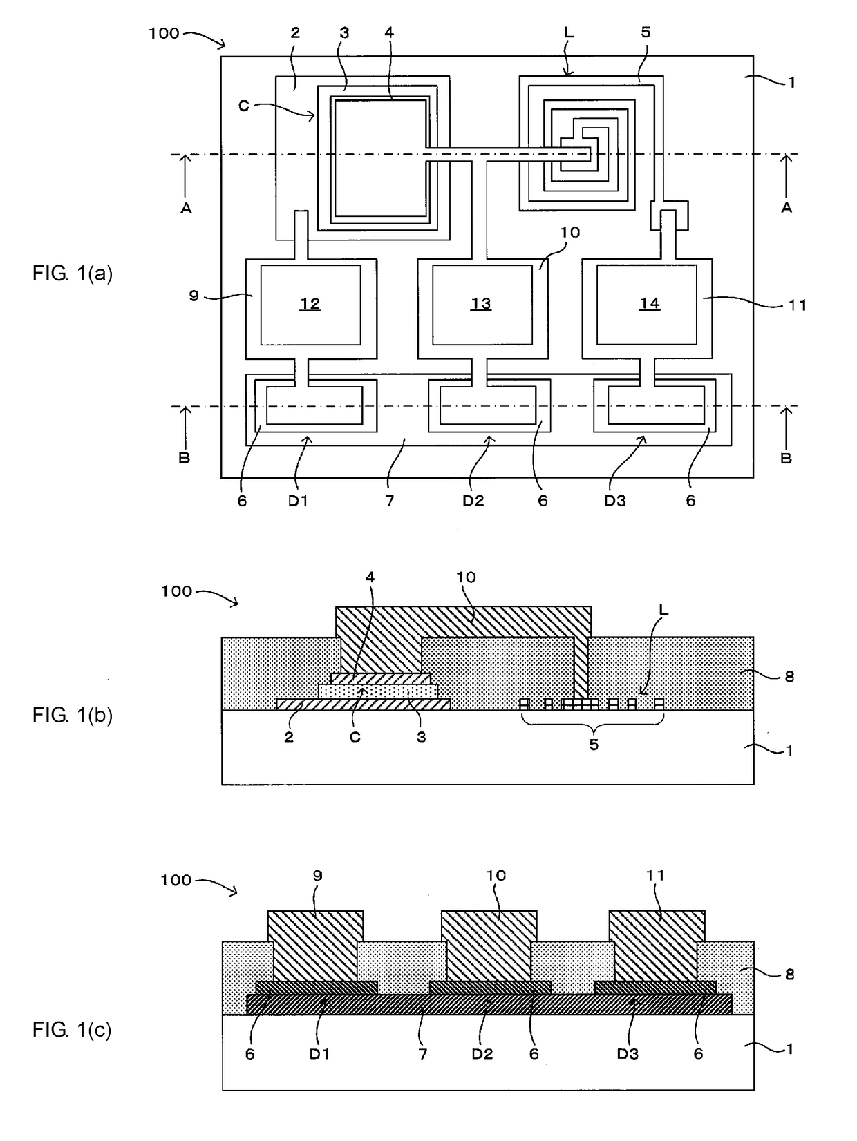
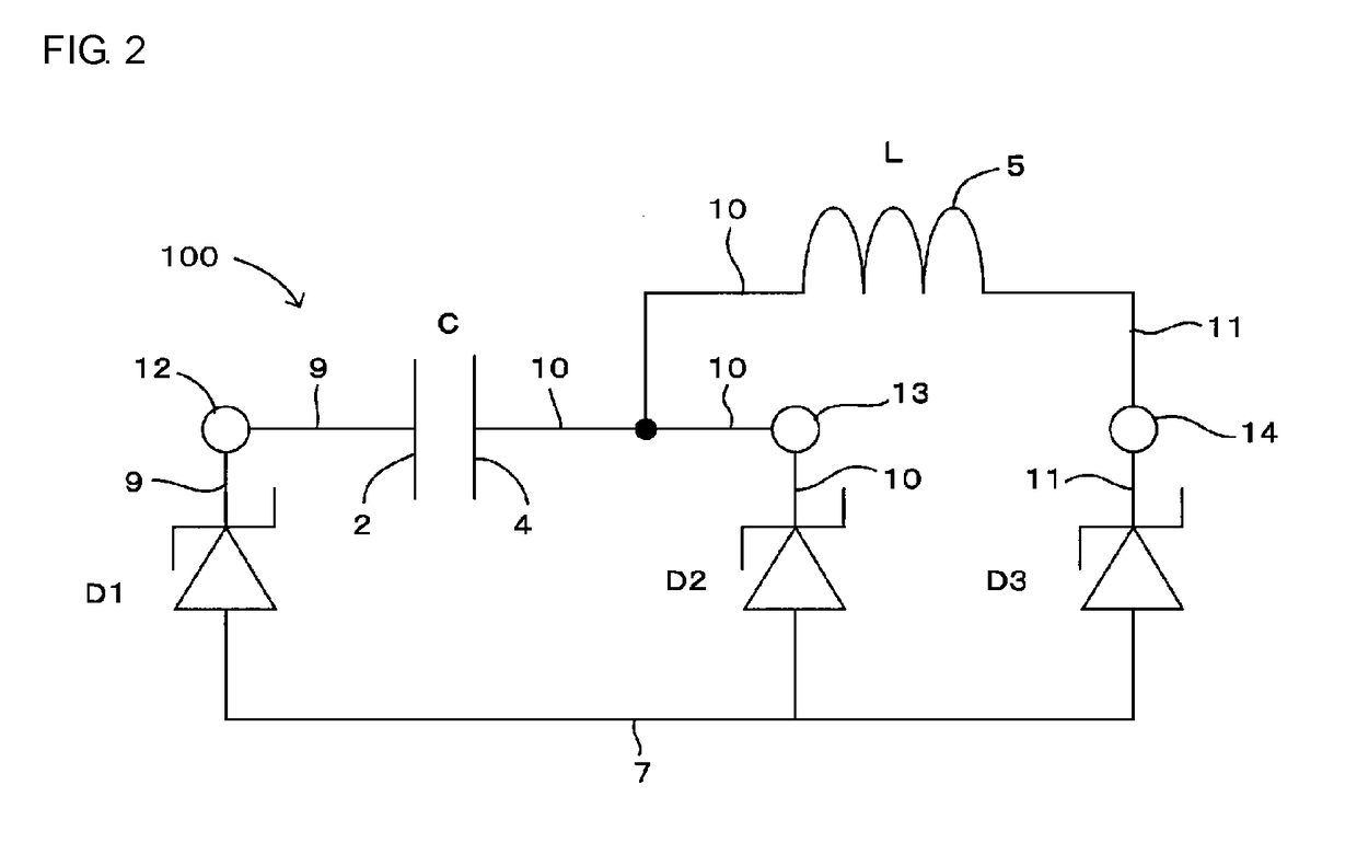
[0043]A first embodiment will be described with reference to FIG. 1(a) to FIG. 4(c). In particular, FIGS. 1(a) to 1(c) illustrate an ESD-protective-function-equipped composite electronic component according to the first embodiment, where FIG. 1(a) is a plan view, FIG. 1(b) is a cross-sectional view taken along line A-A of FIG. 1(a), and FIG. 1(c) is a cross-sectional view taken along line B-B of FIG. 1(a). FIG. 2 is a diagram illustrating an equivalent circuit of the ESD-protective-function-equipped composite electronic component illustrated in FIGS. 1(a)-1(c).

[0044]FIGS. 3(a) to 3(c) illustrate an example of a method for manufacturing the ESD-protective-function-equipped composite electronic component, FIG. 3(a) is a plan view, FIG. 3(b) is a cross-sectional view taken along line A-A of FIG. 3(a), and FIG. 3(c) is a cross-sectional view taken along line B-B of FIG. 3(a). FIGS. 4(a) to 4(c) illustrate an example of a method for manufacturing the ESD-protective-function-equipped comp...

second embodiment

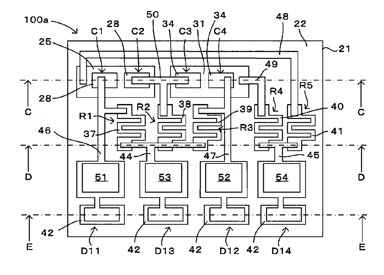
[0072]A second embodiment will be described in the following with reference to FIG. 5 to FIG. 11(d). In particular, FIG. 5 is a plan view illustrating an ESD-protective-function-equipped composite electronic component according to the second embodiment of the present disclosure. FIGS. 6(a) to 6(c) illustrate the ESD-protective-function-equipped composite electronic component illustrated in FIG. 5. FIG. 6(a) is a cross-sectional view taken along line C-C of FIG. 5, FIG. 6(b) is a cross-sectional view taken along line D-D of FIG. 5, and FIG. 6(c) is a cross-sectional view taken along line E-E of FIG. 5. FIG. 7 is a diagram illustrating an equivalent circuit of the ESD-protective-function-equipped composite electronic component illustrated in FIG. 5.

[0073]FIGS. 8(a) to 8(d) illustrate an example of a method for manufacturing the ESD-protective-function-equipped composite electronic component. FIG. 8(a) is a plan view, FIG. 8(b) is a cross-sectional view taken along line C-C of FIG. 8(a...


PUM

PropertyMeasurementUnit
thicknessaaaaaaaaaa
thicknessaaaaaaaaaa
thicknessaaaaaaaaaa

Abstract

An ESD-protective-function-equipped composite electronic component is provided that includes multiple Zener diodes formed from first and second semiconductor layers. Moreover, the second semiconductor layers are disposed on an insulating substrate and in the same plane. The electronic component includes electrodes extending from each of the Zener diodes and one or more thin-film circuit element connected in series between a pair of the electrodes.

Description

CROSS REFERENCE TO RELATED APPLICATIONS[0001]The present application is a continuation of PCT / JP2015 / 070757 filed Jul. 22, 2015, which claims priority to Japanese Patent Application No. 2014-149598, filed Jul. 23, 2014, the entire contents of each of which are incorporated herein by reference.FIELD OF THE INVENTION[0002]The present invention relates to an ESD-protective-function-equipped composite electronic component that has a protective function against an overvoltage caused by electrostatic discharge or the like.BACKGROUND OF THE INVENTION[0003]An conventional ESD-protective-function-equipped composite electronic component 500 illustrated in FIG. 12 and FIG. 13 includes a thin-film capacitor 505 that includes a first capacitor electrode layer 502 stacked on an insulating substrate 501, a dielectric layer 503 stacked on the first capacitor electrode layer 502, and a second capacitor electrode layer 504 stacked on the dielectric layer 503. In addition, the ESD-protective-function-...

Claims


Application Information

Patent Timeline
Patent Type & Authority Applications(United States)
IPC IPC(8): H01L27/02H01L27/13H01L27/01H01L29/866
CPCH01L27/0248H01L29/866H01L27/13H01L28/20H01L28/40H01L28/10H01L27/016H01L27/0255H01L29/1604
Inventor NOMURA, MASANOBUTAKESHIMA, YUTAKA
Owner MURATA MFG CO LTD
Why Eureka
Try Eureka