Method of detecting liquid residual quantity, failure detection device, liquid consuming apparatus, and liquid container

a technology of failure detection and liquid container, which is applied in the direction of material analysis, printing, instruments, etc., can solve the problems of increasing the manufacturing cost of the liquid container, and the inability to detect an erroneous operation of the detection unit,

Inactive Publication Date: 2007-08-16
SEIKO EPSON CORP
View PDF2 Cites 7 Cited by
  • Summary
  • Abstract
  • Description
  • Claims
  • Application Information

AI Technical Summary

Benefits of technology

[0022] With this configuration, when a sufficient liquid residual quantity exists in the liquid containing chamber, the volume of the liquid detection chamber is increased regardless of pressurization or unpressurization by the pressure unit. Accordingly, the volume of the liquid detection chamber is reduced from a time when the inflow of the liquid from the liquid containing chamber stops, that is, when the liquid is exhausted.
[0023] Accordingly, even though pressurization or unpressurization to the liquid containing chamber by the pressure unit is repeated according to the supply of the liquid, the volume of the liquid detection chamber is not reduced, and the volume of the liquid detection chamber does not repeatedly change. Therefore, in a flexible film that constitutes a part of a sensor chamber, wear due to repetitive change is prevented.
[0030] With this configuration, when a sufficient liquid residual quantity exists in the liquid containing chamber, the volume of the liquid detection chamber is increased regardless of pressurization or unpressurization by the pressure unit. Accordingly, the volume of the liquid detection chamber can be reduced from a time when the inflow of the liquid from the liquid containing chamber stops, that is, when the liquid is exhausted.
[0031] Accordingly, even though pressurization or unpressurization to the liquid containing chamber by the pressure unit is repeated according to the supply of the liquid, the volume of the liquid detection chamber is not reduced, and the volume of the liquid detection chamber does not repeatedly change. Therefore, in a flexible film that constitutes a part of a sensor chamber, wear due to a repetitive change is prevented.
[0033] With this configuration, a liquid residual quantity of the liquid container can be detected by the detection unit, and the malfunction of the detection unit can be checked. Therefore, the ejection head can be reliably prevented from being damaged due to idle printing.
[0050] According to the liquid consuming apparatus of the third aspect of the invention, the ejection head can be reliably prevented from being damaged due to idle printing.

Problems solved by technology

However, in order to prevent the liquid ejection head from being damaged due to idle printing, it is necessary to monitor a liquid residual quantity in the container.
Accordingly, the flexible film needs to be formed of an expensive material having high durability, which causes an increase in Manufacturing cost of the liquid container.
Accordingly, while the liquid consuming apparatus is used, it may be impossible to detect an erroneous operation of the detection unit that repeatedly detects presence of the liquid even though the liquid is exhausted.

Method used


Image

  • Method of detecting liquid residual quantity, failure detection device, liquid consuming apparatus, and liquid container
  • Method of detecting liquid residual quantity, failure detection device, liquid consuming apparatus, and liquid container
  • Method of detecting liquid residual quantity, failure detection device, liquid consuming apparatus, and liquid container

Examples


Embodiment Construction

[0060] Hereinafter, a preferred embodiment of a method of detecting a liquid residual quantity, a failure detection device, and a liquid consuming apparatus according to the invention will be described in detail with reference to the accompanying drawings.

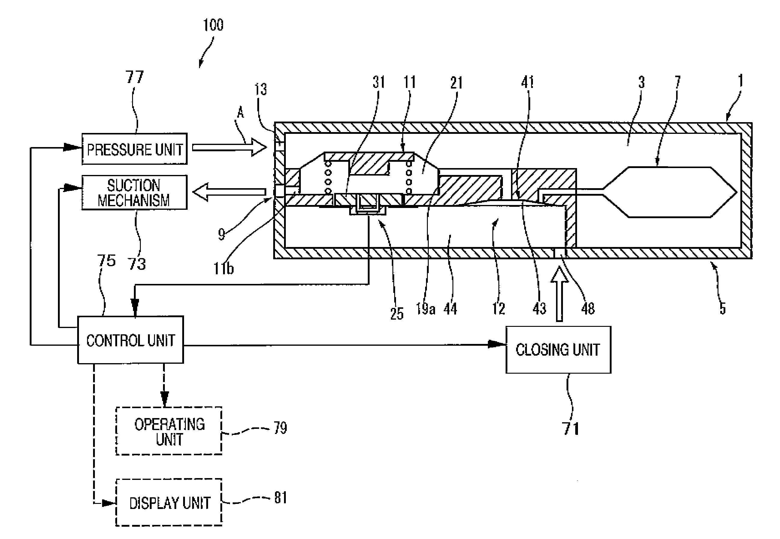
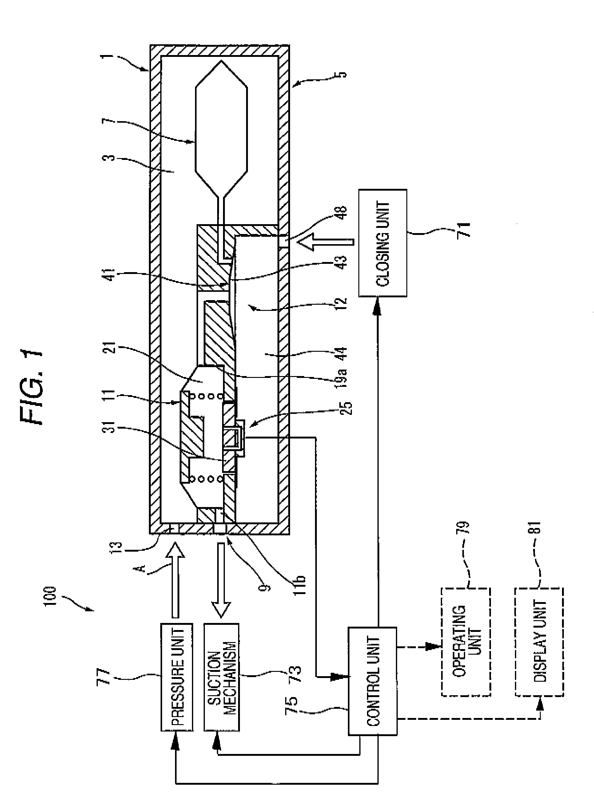
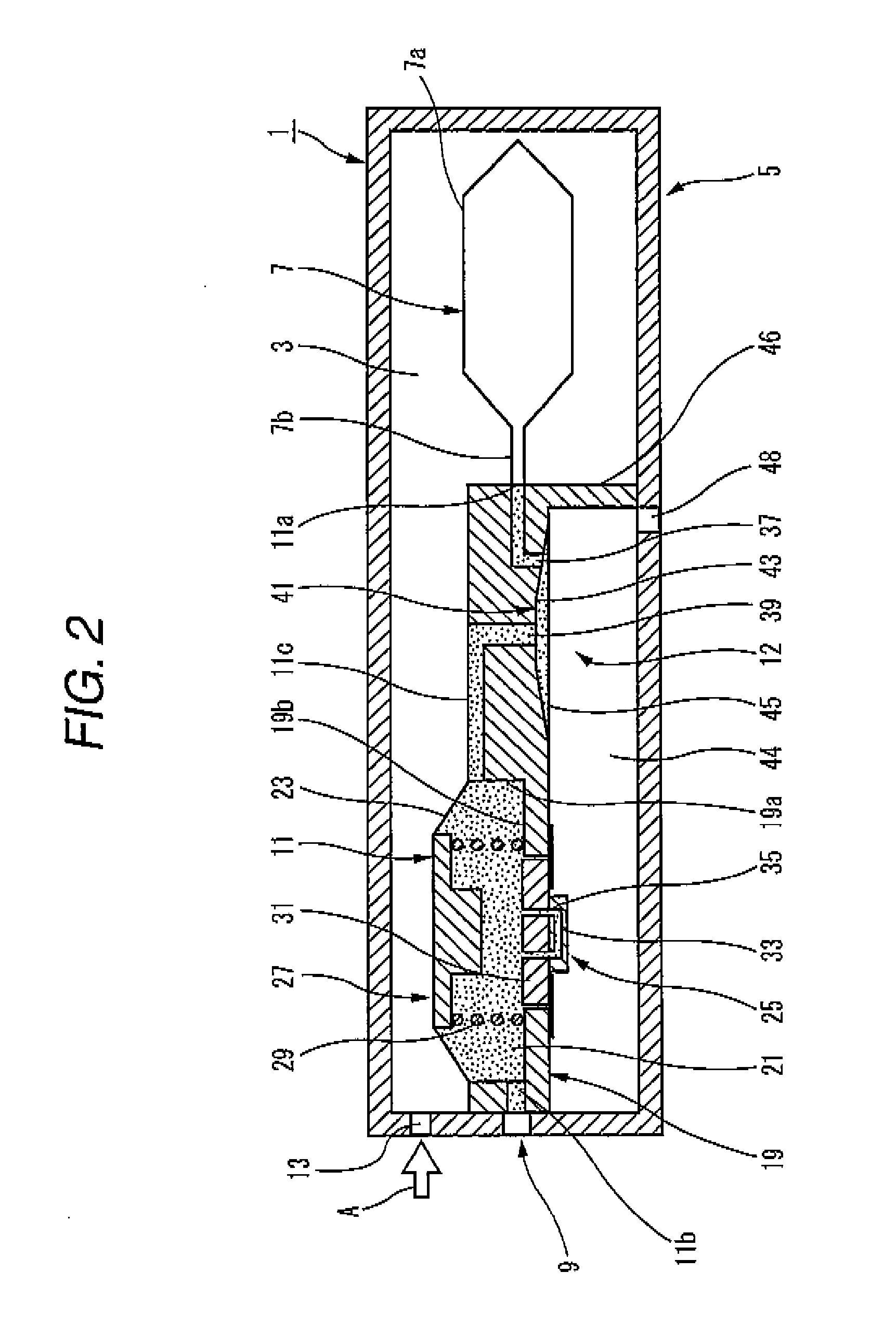
[0061]FIG. 1 is a block diagram of a failure detection device according to an embodiment of the invention. FIG. 2 is a longitudinal cross-sectional view of a liquid container as a subject for failure detection. FIG. 3 is a longitudinal cross-sectional view of a liquid container when a liquid of a liquid containing chamber becomes an exhaustion state. FIG. 4 is a longitudinal cross-sectional view of a liquid container when an on / off valve mechanism is closed and the liquid container becomes a pseudo liquid exhaustion state. FIG. 5 is a flowchart showing a procedure of a method of detecting a failure in the failure detection device shown in FIG. 1.

[0062] In this embodiment, a description will be given by way of a method of detectin...


PUM

PropertyMeasurementUnit
residual quantityaaaaaaaaaa
volumeaaaaaaaaaa
pressureaaaaaaaaaa

Abstract

A method of detecting a liquid residual quantity in a liquid container, the liquid container including: a supply port through which a liquid is supplied to a liquid consuming apparatus; a liquid containing chamber that discharges the liquid stored therein through a liquid discharge port; a liquid detection chamber that is connected to the liquid containing chamber, a volume of which can be increased according to an inflow of the liquid from the liquid containing chamber and can be reduced when the inflow of the liquid from the liquid containing chamber stops; a detection unit for detecting a change of the volume of the liquid detection chamber; and a valve mechanism that is disposed between the liquid containing chamber and the liquid detection chamber and can block the inflow of the liquid from the liquid containing chamber to the liquid detection chamber, and wherein the detection unit performs a detection operation in a state where the volume of the liquid detection chamber is reduced by sucking the liquid in the liquid detection chamber through the supply port while the valve mechanism is closed and in a state where the valve mechanism is opened.

Description

BACKGROUND [0001] 1. Technical Field [0002] The present invention relates to a method of detecting a failure in a detection unit that is provided in a liquid container for supplying a liquid, such as ink, to a liquid consuming apparatus, such as a liquid ejection head for ejecting a minute amount of liquid droplet, to a failure detection device, to a liquid consuming apparatus, and to a liquid container. [0003] 2. Related Art [0004] A liquid ejection head of a textile printing apparatus, a micro dispenser, or a commercial recording apparatus that requires ultrahigh printing quality receives a liquid ejected from a liquid container that is detachably mounted on an apparatus main body. However, in order to prevent the liquid ejection head from being damaged due to idle printing, it is necessary to monitor a liquid residual quantity in the container. [0005] There are suggested various methods that detect an ink residual quantity of an ink cartridge as a liquid container used in a recor...

Claims


Application Information

Patent Timeline
Patent Type & Authority Applications(United States)
IPC IPC(8): G01N1/00
CPCB41J2/17513Y10T436/25B41J2002/17516B41J2/17566
Inventor KIMURA, HITOTOSHI
Owner SEIKO EPSON CORP
Why Eureka
Try Eureka