Vehicle control system

a vehicle control and vehicle technology, applied in the direction of process control, pedestrian/occupant safety arrangement, instruments, etc., can solve the problems of unduly slow vehicle, and the inability of vehicle speed control to assist the driver of the vehicle in his/her drive operation

Active Publication Date: 2007-08-16
DENSO CORP
View PDF27 Cites 52 Cited by
  • Summary
  • Abstract
  • Description
  • Claims
  • Application Information

AI Technical Summary

Benefits of technology

[0008]The present invention addresses the above disadvantages. Thus, it is an objective of the present invention to provide a vehicle control system, which decelerates a vehicle such that the vehicle travels along a curve of a road with a vehicle speed, with which

Problems solved by technology

However, when the vehicle speed V0 is larger than the possible traveling vehicle speed, the vehicle speed control means in the above vehicle control system does not set a target vehicle speed to automatically decelerate the vehicle such that the vehicle travels with the target vehicle speed.
Therefore, there is a possibility that the vehicle is unduly decelerated by the automat

Method used


Image

  • Vehicle control system
  • Vehicle control system
  • Vehicle control system

Examples


first embodiment

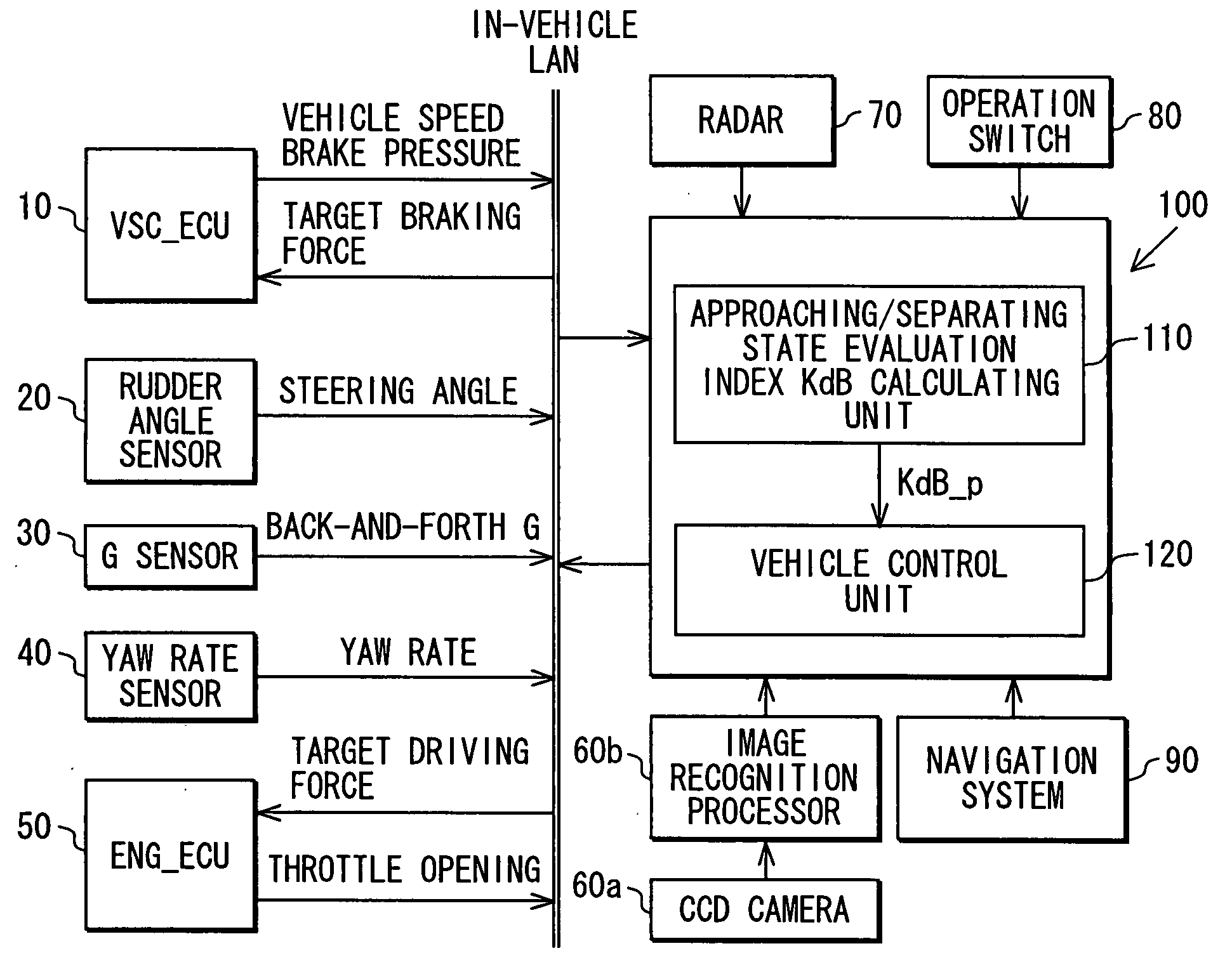
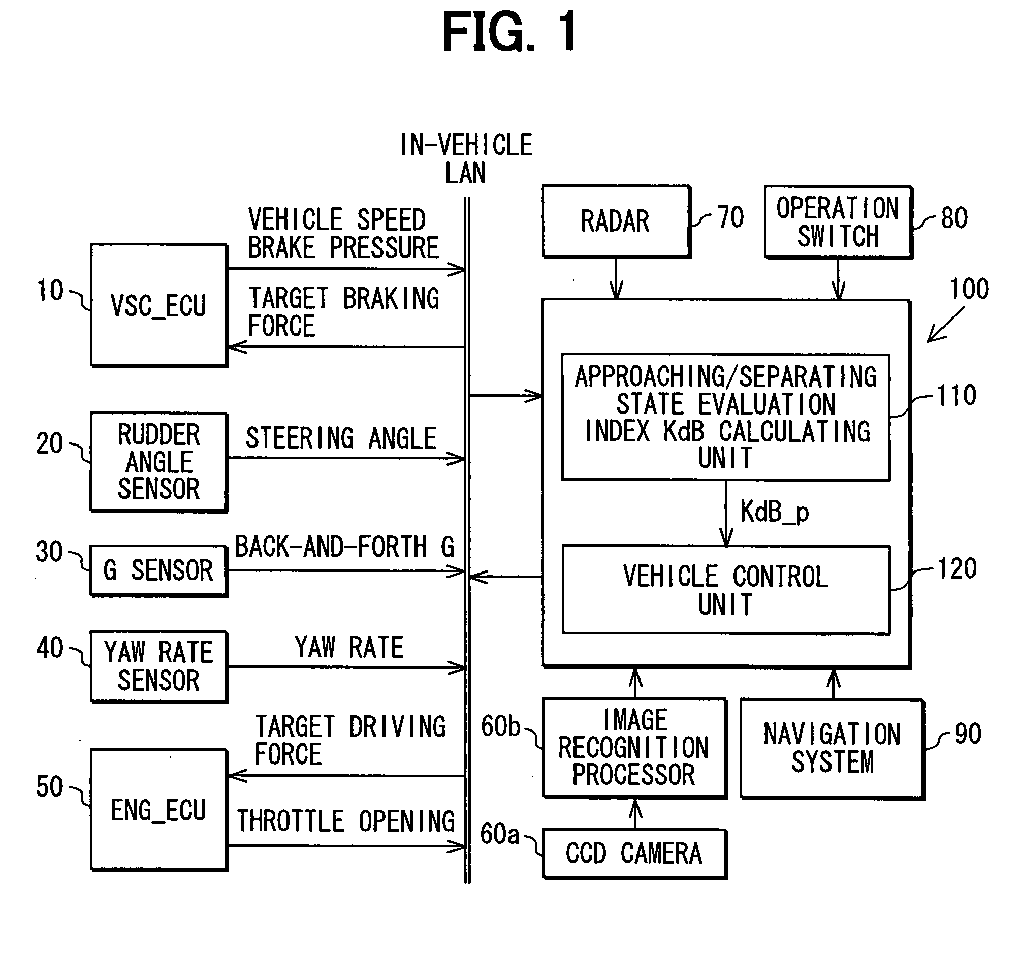
[0036]FIG. 1 shows an overall configuration of a vehicle drive assist system according to a first embodiment. As shown in FIG. 1, the vehicle drive assist system includes a VSC_ECU 10, a rudder angle sensor 20, a G sensor 30, a yaw rate sensor 40, an ENG_ECU 50, a CCD camera 60a, an image recognition processor 60b, a radar 70, an operation switch 80, a navigation system 90, and a curve travel ECU 100.

[0037]The VSC_ECU 10 controls a brake actuator (not shown) that applies braking force to a vehicle, and has a function of controlling a Vehicle Stability Control (VSC; a registered trademark) that controls skidding of the vehicle. The VSC_ECU 10 receives information about target braking force from an in-vehicle LAN, and controls the brake actuator to generate the target braking force. Moreover, the VSC_ECU 10 transmits information about a speed (a vehicle speed) Vs0 of the vehicle and a brake pressure to the in-vehicle LAN. The rudder angle sensor 20 detects information about a steering...

first modification

(First Modification)

[0082]The target lateral acceleration Gy may be set differently according to a size of the curvature radius R of the curve. As a result, the driver can be assisted in performing the drive operation in a sporty manner.

second modification

(Second Modification)

[0083]Moreover, when the driver keeps the steering of the vehicle at a constant steering angle, for example, the target vehicle speed Vs0—t may be set at 0 (zero) to control the vehicle to decelerate.


PUM


Abstract

When a vehicle travels along a curve of a road, a target vehicle acceleration/deceleration that is used for accelerating/decelerating the vehicle to a target vehicle speed, which is set for the curve, is calculated. Based on a comparison between a present vehicle speed of the vehicle and the target vehicle speed, the vehicle is controlled such that an acceleration/deceleration of the vehicle coincides with the target vehicle acceleration/deceleration.

Description

CROSS REFERENCE TO RELATED APPLICATION[0001]This application is based on and incorporates herein by reference Japanese Patent Application No. 2006-35566 filed on Feb. 13, 2006, Japanese Patent Application No. 2006-130631 filed on May 9, 2006, and Japanese Patent Application No. 2006-228374 filed on Aug. 24, 2006.BACKGROUND OF THE INVENTION[0002]1. Field of the Invention[0003]The present invention relates to a vehicle control system.[0004]2. Description of Related Art[0005]A vehicle control system, which determines a shape of a road that is ahead of a vehicle and controls a speed of the vehicle, is conventionally proposed (e.g., JP3432881B2). According to the vehicle control system in JP3432881 B2, when the vehicle is decelerated with a predetermined deceleration from a vehicle speed V0, a distance (a foreseen distance), which is traveled until the vehicle stops within a predetermined time t2, is determined. A tentative vehicle position is set at a position ahead of the vehicle with ...

Claims


Application Information

Patent Timeline
IPC IPC(8): G05D1/00B60R21/00B60T7/12B60T8/1763B60W30/20G08G1/16
CPCB60T7/22G08G1/16B60T2201/022B60T2201/08B60T2201/081B60T2201/16B60T2210/24B60T2210/32B60W30/02B60W30/16B60W40/072B60W40/076B60W2420/52B60W2550/143B60T8/1755B60W2552/20B60W2552/30G08G1/166G08G1/167
Inventor ISAJI, KAZUYOSHITSURU, NAOHIKO
Owner DENSO CORP
Why Eureka
Try Eureka