
Trowel

a technology of trowels and troughs, which is applied in the field of improved construction of trowels, can solve the problems of reducing work efficiency, unrotatable handle, and inability to replace the float, and achieve the effect of improving handling comfortability and stability

Inactive Publication Date: 2007-08-23
HO CHING YI
View PDF3 Cites 18 Cited by
  • Summary
  • Abstract
  • Description
  • Claims
  • Application Information

AI Technical Summary

Benefits of technology

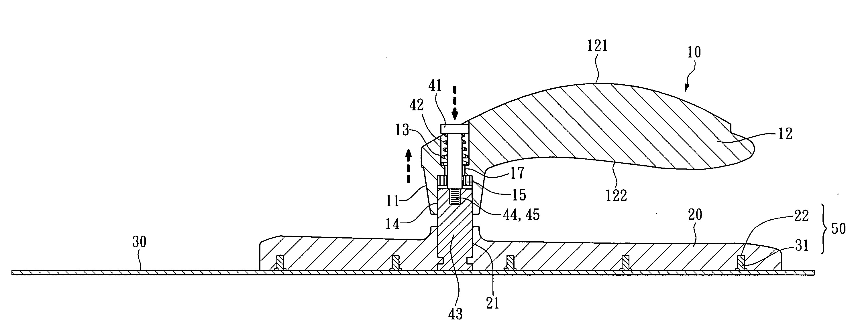
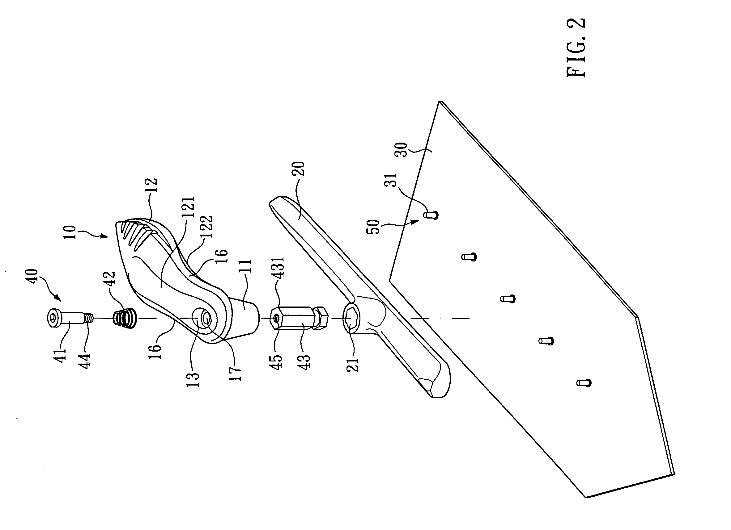
[0009] A trowel comprises a handle, a blade and a tongue therebetween. The handle is connected with the tongue by a pivot structure such that it is capable of rotating around a pivot shaft and can be orientated in a desired position thereon. The tongue is further connected to the blade through a fixing structure, which allows the tongue and blade to be combined or separated with each other.
[0010] It is one object of the present invention to provide a trowel with a rotatable handle that can be positioned in any desired direction around said pivot structure such that a user can operate the trowel at will and keeps comfortable holding gesture without respect to different working surfaces.
[0011] It is another object of the present invention to provide a trowel, in which the float can be replaced to meet operational needs.
[0012] It is still another object of the present invention to provide a trowel in which the handle is ergonomically designed to provide improved comfortability and stability for handling.

Problems solved by technology

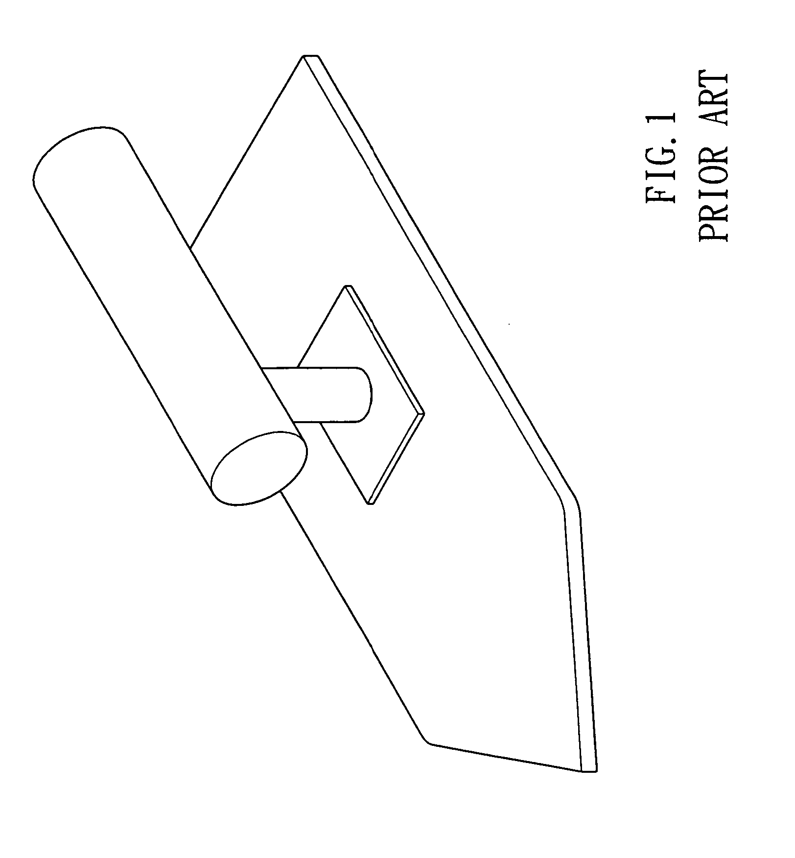
As the float and handle are integrated firmly, there is one of the disadvantages of a conventional trowel that the handle is unrotatable and there is another disadvantage that the float is not replaceable.
In consequence, an inappropriate holding gesture may not only reduce the efficiency of work but also result relatively deteriorated resultant surface.
It may even cause occupational injury to the user for such an inappropriate holding gestures lasting long term.
Further it would be inconvenient for a user to prepare and carry various trowels while the float is unreplaceable.

Method used


Image

  • Trowel
  • Trowel
  • Trowel

Examples


Embodiment Construction

[0022] Please refer to FIGS. 2, 3 and 4. A trowel according to the present invention comprises:

[0023] a handle 10 which is one-piece formed composed by a connecting section 11 and a handling section 12; wherein, said handling section 12 has a substantially arched and parabolic upper surface 121 which makes the distance from upper surface 121 to lower surface 122, in other words, the thickness of the handling section 12 increased in the middle part correspondingly; wherein, each side edge of said handling section 12 has a center-forward arched indentation 16 disposed relatively near the connecting section 11; wherein, the connecting section 11 extends downward vertically against the handle 10 for a predetermined length with a shaft-tube appearance.

[0024] a tongue 20;

[0025] a blade 30;

[0026] a pivot structure 40 provided for connecting said tongue 20 to said connecting section 11 where allows the handle 10 being pivoted on the pivot structure 40 and positioned in a desired positio...


PUM


Abstract

A trowel comprises a handle, which is combined with a tongue that is further combined with a blade. Said handle and tongue are connected through a pivot structure such that the handle can pivot thereon and be positioned at a desired position. Further, a blade-fixing structure allows said tongue and blade to be combined or separated with each other.

Description

BACKGROUND OF THE INVENTION [0001] 1. Field of the Invention [0002] The present invention relates to hand tools and, more particularly, to an improved construction of a trowel. [0003] 2. Description of Related Art [0004] Referring to FIG. 1, a conventional trowel typically consists of a handle fastened on a float. [0005] As the float and handle are integrated firmly, there is one of the disadvantages of a conventional trowel that the handle is unrotatable and there is another disadvantage that the float is not replaceable. [0006] An unrotatable handle is typically fixed on the float in the direction parallel to the axis of the float. Once a user intends to change the operating angle and direction, it is necessary for the user to change the holding gesture to accommodate the trowel to the working surface. In consequence, an inappropriate holding gesture may not only reduce the efficiency of work but also result relatively deteriorated resultant surface. It may even cause occupational...

Claims


Application Information

Patent Timeline
Patent Type & Authority Applications(United States)
IPC IPC(8): B05C17/10
CPCB25G1/06E04F21/163
Inventor HO, CHING-YI
Owner HO CHING YI
Learn More