Apparatus and method for rotating a cap relatively to a container

a technology of apparatus and container, applied in the direction of caps, closures using caps, caps, etc., can solve the problems of discs that cannot adjust the relative torque applied to the caps relatively precisely, discs that wear relatively fast, and destabilize the containers

Active Publication Date: 2007-08-23
NJM PACKAGING INC
View PDF15 Cites 22 Cited by
  • Summary
  • Abstract
  • Description
  • Claims
  • Application Information

AI Technical Summary

Benefits of technology

[0010] Advantageously, the claimed invention may use cap engaging components having engaging surfaces that move at relatively low speeds. Therefore, this reduces the wear of the belts as a difference between the speed of a cap that is engaged and the belt is relatively small.

Problems solved by technology

This causes the discs to wear relatively fast.
In addition, having discs that rotate at a relatively high speed tends to destabilize the container when the cap is engaged as an impact produced onto the cap by the discs is then transmitted to the container.
Furthermore, when a cap is screwed onto a container, the discs typically do not allow adjusting relatively precisely a torque applied to the cap.
Once again, achieving a relatively precise torque when screwing the cap is relatively hard to achieve using these types of devices.
Therefore, it is relatively hard to select belt speeds that are suitable for both rotating the cap relatively fast when the cap is initially screwed onto the container and producing a relatively slow rotation of the cap when the cap is almost entirely screwed onto the container.
Indeed, as the cap is screwed onto the container, a torque applied by the rotating cap onto the container increases.
A slipping belt wears off prematurely, may damage the cap and may destabilize the container.

Method used


Image

  • Apparatus and method for rotating a cap relatively to a container
  • Apparatus and method for rotating a cap relatively to a container
  • Apparatus and method for rotating a cap relatively to a container

Examples


Embodiment Construction

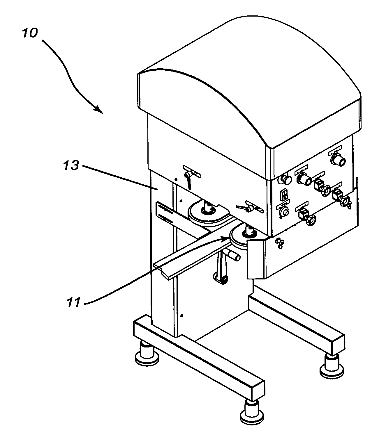
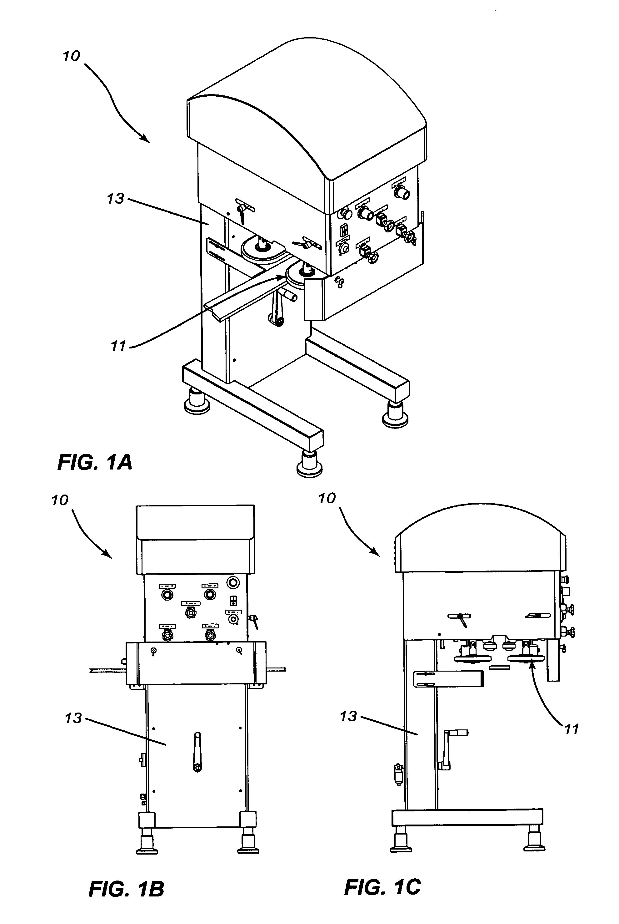
[0035]FIGS. 1A, 1B and 1C illustrates an apparatus 10 for rotating a cap 12 (not shown in FIGS. 1A, 1B and 1C) relatively to a container 14 (not shown in FIGS. 1A, 1B and 1C). The apparatus 10 includes a cap screwing assembly 11 mounted to a frame 13. In some embodiments of the invention, the frame 13 allows for the adjustment of a height above a ground surface at which the cap screwing assembly 11 is located.

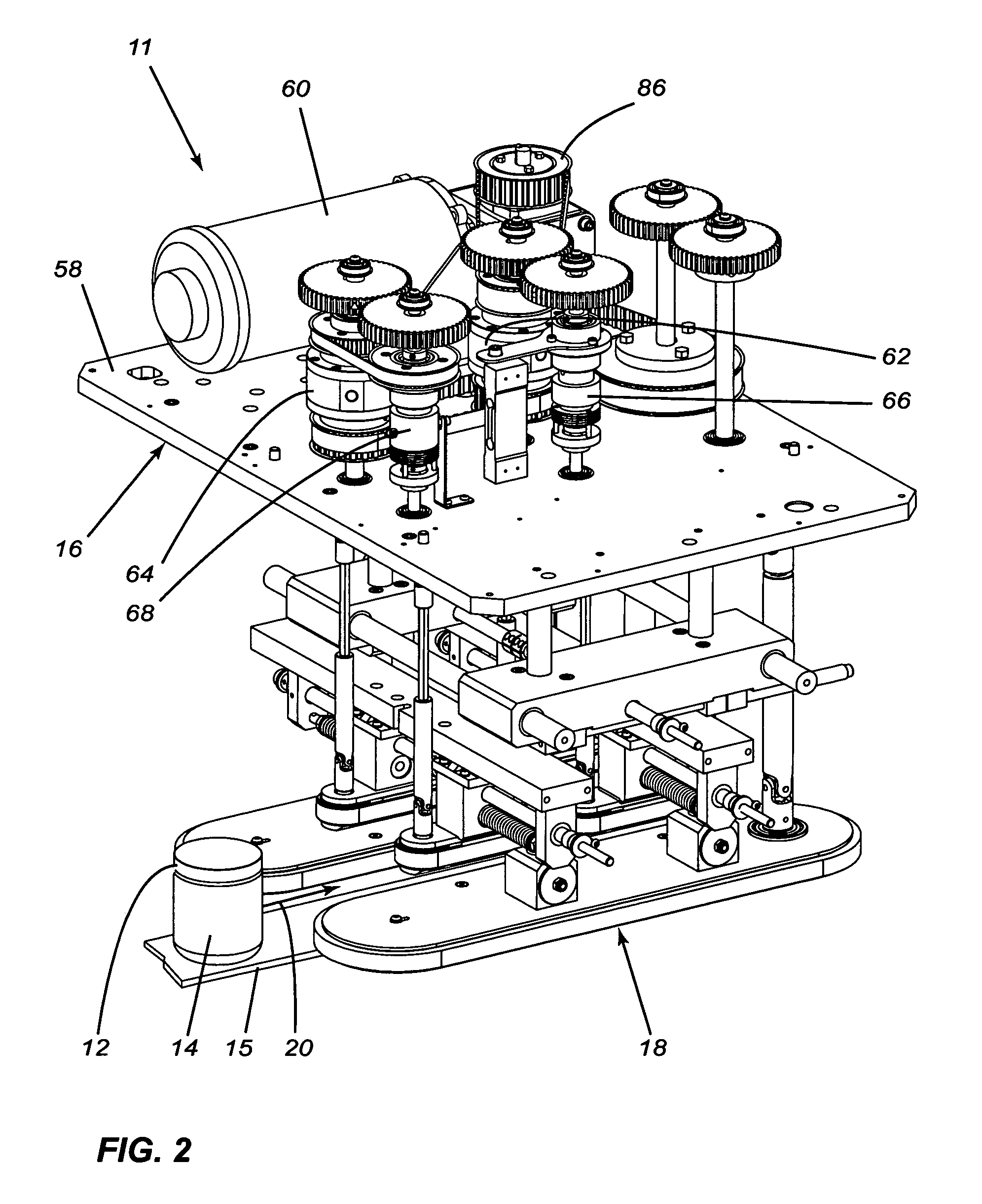
[0036] Referring to FIG. 2, the container 14 moves along a predetermined path at a container speed generally indicated by the reference numeral 20. For example, as seen in the drawings, the container 14 moves onto a sliding rail 15 that defines the predetermined path and supports the container 14. However, it is within the scope of the invention to support the container in any other suitable manner.

[0037] The cap screwing assembly includes a driving stage 16 and a driven stage 18. The driving stage 16 is coupled to the driven stage 18 so that power is provided to components o...


PUM


Abstract

An apparatus for rotating a cap relatively to a container. The container moves along a predetermined path at a container speed. The cap has a first and a second cap engagement location. The first and second cap engagement locations are circumferentially spaced apart relative to each other. The apparatus includes a first cap engaging component, the first cap engaging component including the first component cap engaging surface for engaging the cap at the first cap engagement location and applying a first substantially tangential force thereto. The first cap engaging surface moves at a first speed when substantially in register with the first cap engagement location. A second cap engaging component includes a second component cap engaging surface for engaging the cap at the second cap engagement location and applying a second substantially tangential force thereto. The second cap engaging surface moves at a second speed when substantially in register with the second cap engagement location. The first and second cap engaging components are operatively coupled to each other for maintaining substantially constant the sum of the first and second speed.

Description

FIELD OF THE INVENTION [0001] The present invention relates generally to automated manufacturing lines. More specifically, the present invention is concerned with an apparatus and a method for rotating a cap relatively to a container. BACKGROUND OF THE INVENTION [0002] There exist many apparatuses for rotating caps relatively to a container. For example, such apparatuses are used for screwing caps onto containers or screwing off caps from containers. [0003] Some of these apparatuses include discs that rotate in opposing directions. For example, U.S. Pat. No. 5,918,442 issued to Dewees on Jul. 6, 1999, describes such an apparatus. In these apparatuses, a container is moved toward the discs and the cap is positioned over the container. When the cap reaches the discs, the discs engage the cap and rotate the discs relatively to the container. [0004] Since there is typically a need to rotate the cap by a relatively large angle, the discs must rotate relatively fast because the duration o...

Claims


Application Information

Patent Timeline
Patent Type & Authority Applications(United States)
IPC IPC(8): B65B7/28
CPCB67B3/2046B65B7/2835
Inventor JALBERT, LUC
Owner NJM PACKAGING INC
Why Eureka
Try Eureka