Initiator assembly

a technology of initiator and assembly, which is applied in the direction of electric fuzes, pedestrian/occupant safety arrangements, vehicular safety arrangements, etc., can solve the problems of limiting the range of plastics suitable for insert molding, affecting the operation of micro gas generators, and affecting the quality of gas generators

Inactive Publication Date: 2007-08-23
JOYSON SAFETY SYST ACQUISITION LLC
View PDF29 Cites 20 Cited by
  • Summary
  • Abstract
  • Description
  • Claims
  • Application Information

AI Technical Summary

Problems solved by technology

However, machining these features into the bore seal is relatively expensive.
However, limitations on molding process temperatures and pressures imposed by the structure of the initiator tend to limit the range of plastics suitable for insert molding.
This results in a bore seal having insufficient strength for micro gas generator operation.

Method used


Image

  • Initiator assembly
  • Initiator assembly
  • Initiator assembly

Examples


Embodiment Construction

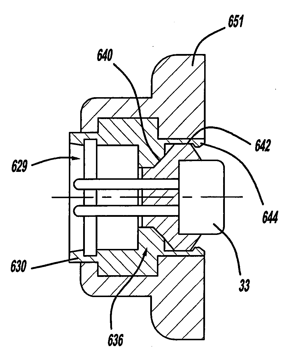
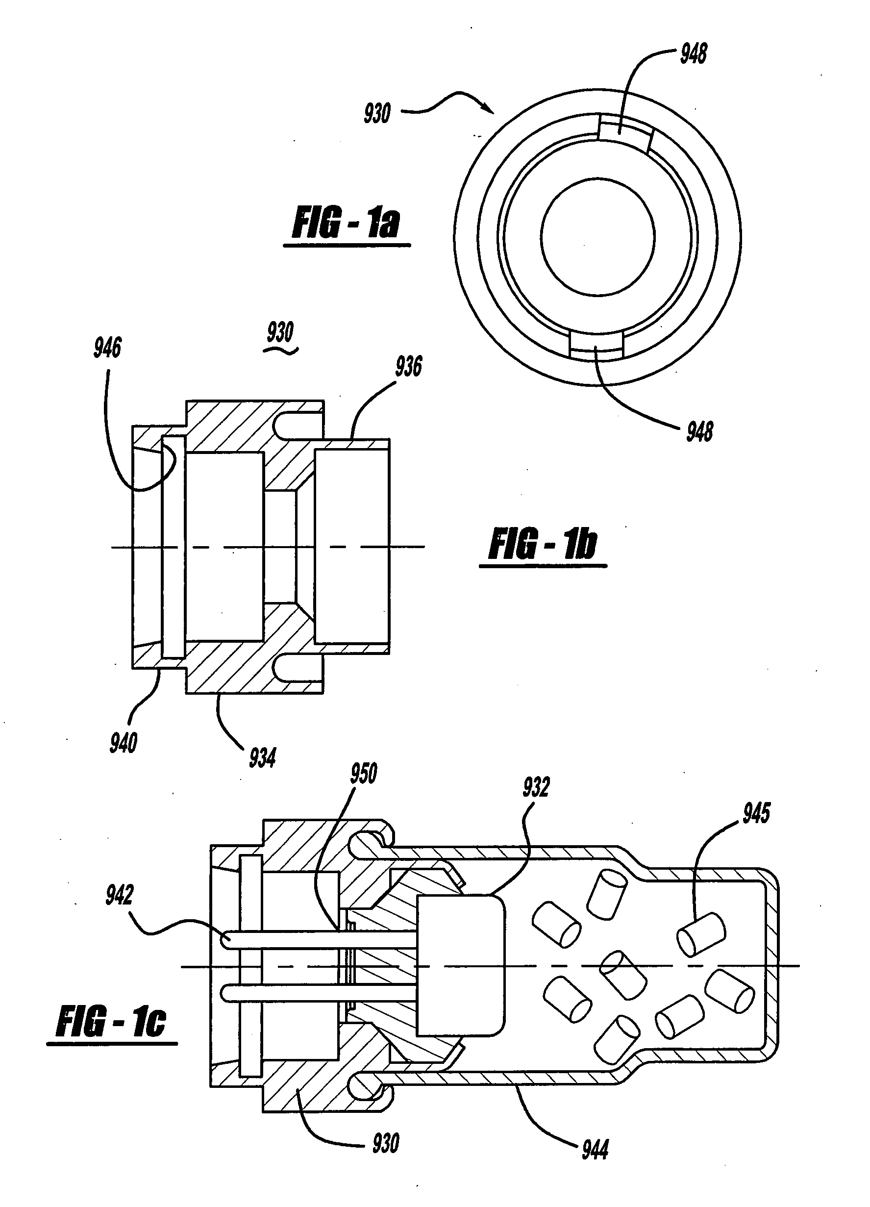
[0011]FIGS. 1a-1c show one embodiment of a conventional bore seal 930 as adapted for incorporation into a micro gas generator. Referring to FIGS. 1a-1c, an initiator or initiator assembly 932 is secured within a bore seal 930 for mounting within an associated element of a vehicle occupant protection system, for example. In the embodiment shown in FIGS. 1a-1c, bore seal 930 includes a body 934 and an annular wall 936 extending in a first direction from body 934 to define a cylindrical cavity for receiving an initiator or initiator assembly 932 therein. Another annular wall 940 extends from body 934 in a second direction, opposite the first direction, to define another cylindrical cavity adapted for housing the initiator electrodes 942. A rear portion of bore seal 930 is configured to provide an interface mateable with a complementary connector of a wiring harness or other suitable initiator activation signal transmission medium. FIG. 1c shows the bore seal 930 of FIGS. 1a and 1b inco...


PUM


Abstract

A bore seal is includes a polymeric interface portion adapted for coupling to an initiator activation signal transmission medium, and an initiator-receiving portion adapted for receiving an initiator therein. The bore seal generally houses a pyrotechnic initiator or igniter therein, for incorporation into a gas generating system or other system having a pyrotechnically actuatable element.

Description

CROSS-REFERENCE TO RELATED APPLICATIONS[0001]This application claims the benefit of U.S. Provisional Application Ser. No. 60 / 774,576 filed on Feb. 17, 2006.BACKGROUND OF THE INVENTION[0002]The present invention relates generally to gas generating systems and, more particularly, to gas generators used in vehicle occupant protection systems and related components, such as seatbelt pretensioners.[0003]Gas generators used in seatbelt pretensioners are known as micro gas generators (MGG's) due to the relatively small size of the gas generator. Exemplary pretensioners using such micro gas generators include those described in U.S. Pat. Nos. 6,460,794, 6,505,790, 6,520,443, and 6,419,177, incorporated herein by reference. Micro gas generators generally include a bore seal for receiving and securing an initiator therein, an initiator including an initiator charge, and a gas generant composition which ignites and burns in response to activation of the initiator to produce gases for actuating...

Claims


Application Information

Patent Timeline
Patent Type & Authority Applications(United States)
IPC IPC(8): F42B3/18B60R22/46
CPCF42B3/107B60R2021/26029
Inventor STEVENS, BRUCE A.
Owner JOYSON SAFETY SYST ACQUISITION LLC
Why Eureka
Try Eureka