Pyrotechnic switching device

a switching device and pyrotechnic technology, applied in the direction of conductor severing switch, explosion switch closing, electric apparatus, etc., can solve the problems of increasing the time required, electric arcs, devices can be subjected, etc., and achieves the effect of high sensitivity and ensuring a very reliable cuto

Active Publication Date: 2021-01-05
MERSEN FRANCE SB
View PDF6 Cites 0 Cited by
  • Summary
  • Abstract
  • Description
  • Claims
  • Application Information

AI Technical Summary

Benefits of technology

[0012]In normal operation (device in the first configuration), the electric current can circulate through the first portion but not through the second portion due to the presence of the insulating segment. Thus, no current passes through the first fuse element in normal operation, thus reducing the aging thereof. When an anomaly is detected, said at least one pyrotechnic initiator is tripped and the first and second protrusions are set in motion. Following this setting in motion, the first portion is disconnected by impact with the first protrusion and the two conductive elements of the second portion are connected by the second protrusion. The disconnection of the first portion allows cutting off the current circulating therein and the connection of the conductive elements authorizes the circulation of the current in the second portion, thereby tripping the first fuse element which permanently cuts off the current in the circuit. The disconnection of the first portion is carried out, simultaneously or subsequently, upon connection of the conductive elements so as to be able to thus divert, towards the second portion, the current circulating initially in the first portion, and thus end the cutoff by tripping of the first fuse element, while avoiding the generation of an electric arc within the second portion.
[0014]The fact of using a fuse core with its insulating shell advantageously allows improving the strength over time of the fuse core, and in particular slowing down the phenomenon of spontaneous opening of the first fuse element, thus further improving the reliability of the cut-off device.
[0017]In this case, upon normal operation of the system, the second fuse element is conducting, the voltage across the second fuse element is relatively low and the current passing through the ignition device of the pyrotechnic initiator is sufficiently low so as not to actuate the latter. On the other hand, when the intensity of the current passing through the second fuse element exceeds the second predetermined value, the second fuse element trips, that is to say its resistance increases producing an increase in the voltage across the second fuse element. The intensity in the ignition device then increases, thus making it possible to actuate the pyrotechnic initiator and switch the device from the first to the second configuration in order to permanently cut off the circulation of the current in the circuit. This characteristic is advantageous in order to have a simplified cut-off solution by proposing an autonomous cut-off device directly integrating the element that will trip the cutoff, in this case the second fuse element. This advantageously allows dispensing with the presence of a third-party voltage / current sensor / analyzer device to allow the tripping of the initiator.
[0019]Such a characteristic is advantageous in order to improve the compactness of the cut-off device. In this case, the cut-off device constitutes a single pyrotechnic switch in which the first and second portions are present inside the same chamber and in which the first and second protrusions protrude from the lower face of the same movable piston.
[0032]It is advantageous to implement a first low-rating fuse element in the system described above because it has a high sensitivity, and thus guarantees a very reliable cutoff.

Problems solved by technology

However, these devices can be subject, in particular when high voltages are used in the electrical circuit, to the formation of electric arcs.
These electric arcs increase the time required to cut off the current in the circuit and generally reduce the reliability of the cut-off device.
After the initiator is tripped and the conductive bar is broken, all the current passes through the fuse, causing it to melt, and permanently cuts off the current in the circuit.
This type of device generally operates effectively but, over time, the fuse can be subject to aging, which can ultimately affect its reliability.

Method used


Image

  • Pyrotechnic switching device
  • Pyrotechnic switching device
  • Pyrotechnic switching device

Examples


Embodiment Construction

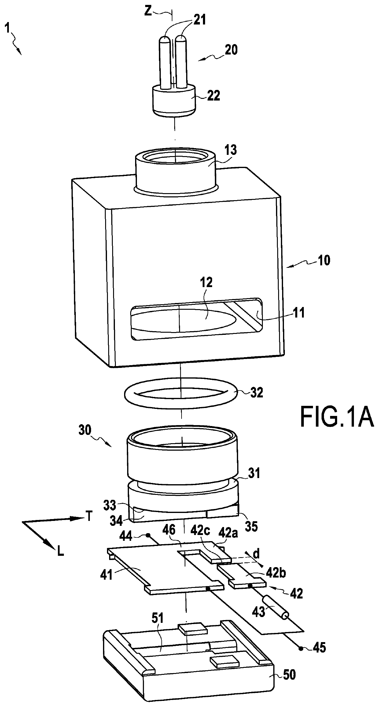
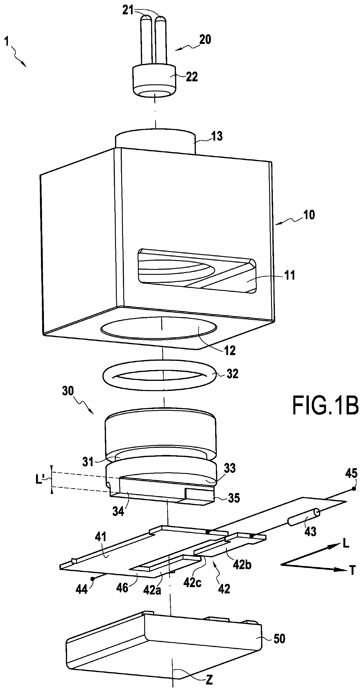
[0044]FIGS. 1A and 1B show two exploded views of a cut-off device 1 according to one embodiment of the invention. The illustrated cut-off device 1 comprises: a body 10, a pyrotechnic initiator 20, a piston 30, a first conductive portion 41, a second portion 42, a first fuse element 43 and a support 50. In the illustrated example, the longitudinal direction L corresponds to the direction along which the portions 41 and 42 extend and connecting the terminals 44 and 45 of the device 1. The transverse direction T is perpendicular to this direction L in the plane of the portions 41 and 42.

[0045]The device 1 comprises a first 44 and a second 45 electrical terminal which are intended to be connected to an electrical circuit to be cut off. The first conductive portion 41 and the second portion 42 are mounted in parallel with each other between the first terminal 44 and the second terminal 45 of the cut-off device. The first conductive portion 41 electrically connects the first terminal 44 t...


PUM


Abstract

A pyrotechnic cut-off device to be connected to an electrical circuit to cut-off, includes a pyrotechnic initiator, a first and a second conductive portion each intended to be connected to the electrical circuit, the second portion being connected in parallel with the first portion and including two conductive elements separated by an insulating segment, at least one of the conductive elements provided with a first fuse element connected in series which is configured to trip when the intensity of the current passing therethrough exceeds a first predetermined value, and a first and a second insulating protrusion, each protruding from a lower face of a movable piston and the first and the second protrusions being located respectively in front of the first portion and the insulating segment. The pyrotechnic initiator is configured to switch the cut-off device from a first current passage configuration to a second current cut-off configuration.

Description

CROSS-REFERENCE TO RELATED APPLICATIONS[0001]This application is the U.S. National Stage of PCT / FR2018 / 052359, filed Sep. 25, 2018, which in turn claims priority to French patent application number 1758899 filed Sep. 26, 2017. The content of these applications are incorporated herein by reference in their entireties.BACKGROUND OF THE INVENTION[0002]The present invention relates to the general field of electrical cut-off devices, and more particularly those of the pyrotechnic actuation type. The invention also relates to an electrical system secured by such a device.[0003]There are known pyrotechnic cut-off devices comprising a body in which a pyrotechnic initiator is present configured, when tripped, to set a piston in motion provided with a protrusion in the direction of a conductive bar to be cut. Documents WO 2016 / 038043 and WO 2016 / 038050 show examples of devices of this type. However, these devices can be subject, in particular when high voltages are used in the electrical circ...

Claims


Application Information

Patent Timeline
Patent Type & Authority Patents(United States)
IPC IPC(8): H01H85/02H01H39/00
CPCH01H85/0241H01H39/004H01H39/006
Inventor MATHIEU, ALEXANDRELORENZON, ROMAINDE PALMA, JEAN-FRANÇOISOUAIDA, RÉMY
Owner MERSEN FRANCE SB
Why Eureka
Try Eureka