An opto-pyrotechnic actuator

a technology of applied in the direction of blasting cartridges, ammunition fuzes, weapons components, etc., can solve the problems of limited lifetime of connection between optical fiber and initiator body made by means of adhesive, mechanical and/or thermal strength of that type of connection is not guaranteed, and the number of parts needed is reduced. , the effect of easy industrialization

Active Publication Date: 2019-11-07
ARIANEGRP SAS
View PDF4 Cites 0 Cited by
  • Summary
  • Abstract
  • Description
  • Claims
  • Application Information

AI Technical Summary

Benefits of technology

[0010]The connection between the optical fiber and the body of the initiator when made in accordance with the method of the invention does not have any organic substances, unlike prior art connections which make use of elastomer gaskets and of a large quantity of adhesion in order to provide structural strength. The connection of the invention is also chemically

Problems solved by technology

That type of connection presents several drawbacks, in particular when the initiator is to be exposed to high temperatures and pressures.
In particular, a connection between an optical fiber and an initiator body made by means of an adhesive possesses a lifetime that is limited because of organic substances that are present in the connection degassing so that the connection degrades over time.
In add

Method used


Image

  • An opto-pyrotechnic actuator
  • An opto-pyrotechnic actuator
  • An opto-pyrotechnic actuator

Examples


Embodiment Construction

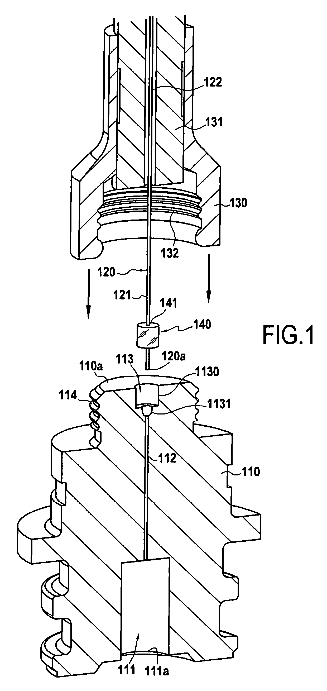
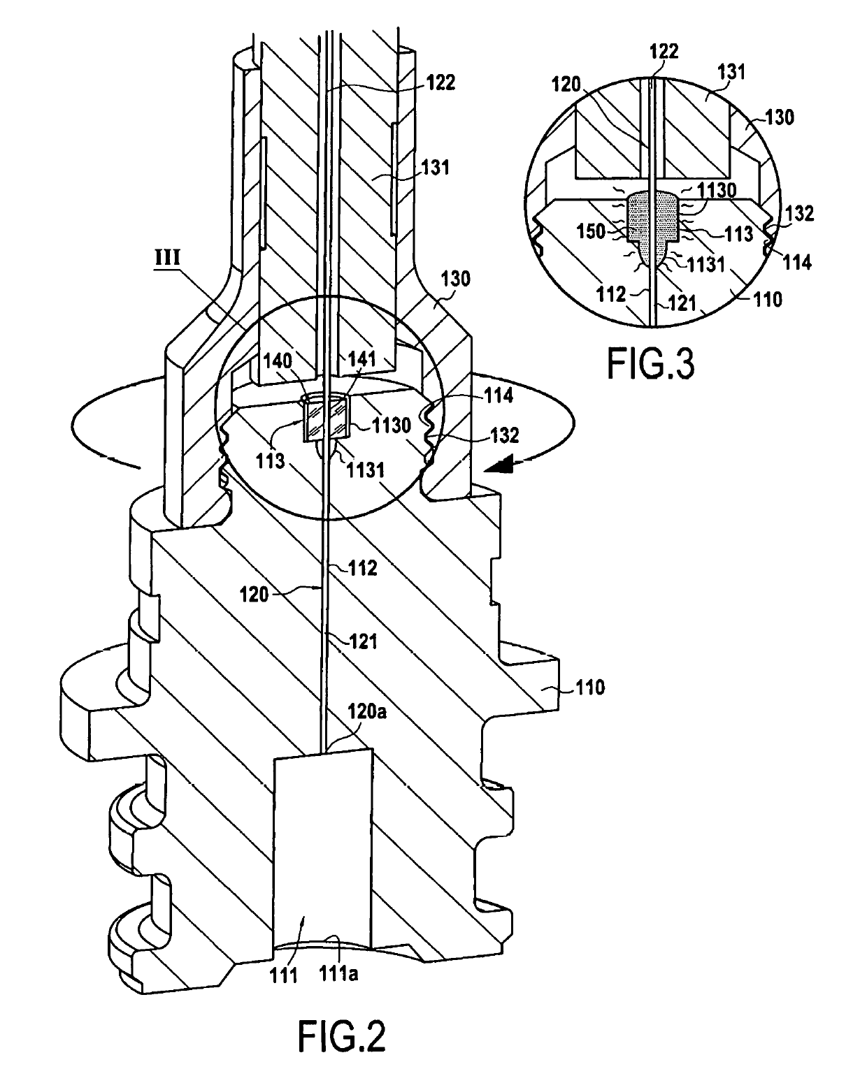
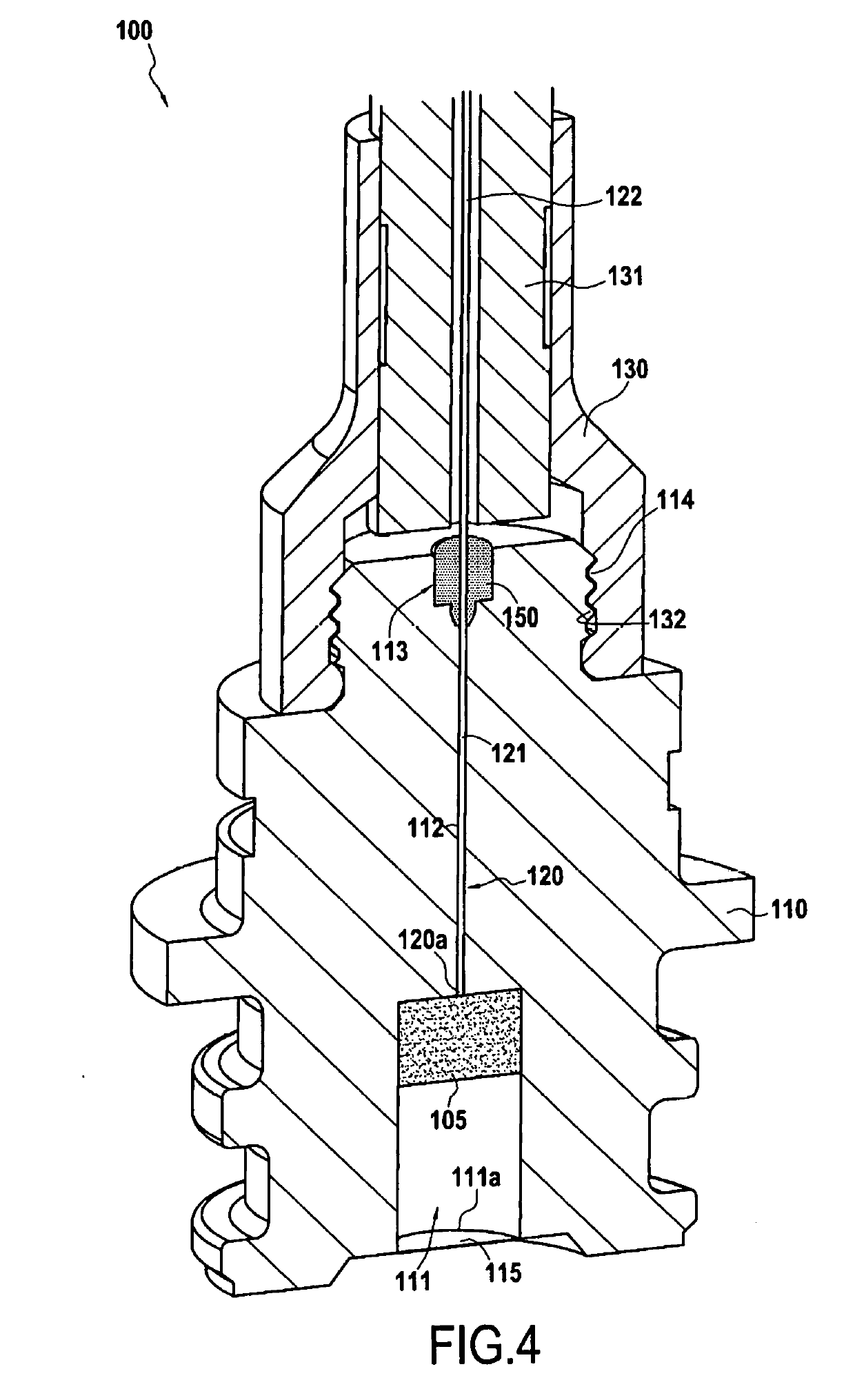
[0022]FIGS. 1 to 4 show the fabrication of an opto-pyrotechnic initiator in accordance with an implementation of the invention. As shown in FIG. 1, the method begins by forming a body 110 having a cavity 111 that is to receive a pyrotechnic composition or charge. The cavity 111 has an opening 111a situated in the bottom portion of the body 110, the opening 111a corresponding to the portion of the body 110 through which the gas generated by the pyrotechnic charge is discharged. The body 110 also has an internal passage 112 extending between the cavity 111 and an inlet 113 leading to the top outside face 110a of the body 110. In this example, the inlet 113 has a cavity 1130 presenting a section (diameter) greater than that of the internal passage 112, the cavity 1130 being connected to the internal passage 112 via a neck 1131 presenting a section that decreases going from the cavity 1130 to the internal passage 112. The body 110 may be made of a metal material such as Inconel, 316 L o...


PUM


Abstract

A method of fabricating an opto-pyrotechnic initiator, includes a) forming a body having a cavity in which a pyrotechnic charge is to be received, the body also having an internal passage extending between the cavity containing the pyrotechnic charge and an inlet opening out in an outside face of the body; b) placing a first portion of an optical fiber in the internal passage of the body, with a second portion of the optical fiber extending beyond the inlet of the body, and a glass preform being interposed between the optical fiber and the inlet of the body; and c) applying heat treatment to the glass preform to raise the glass preform to a temperature higher than the melting point of the glass preform so as to form a hermetic sealing element made of glass between the optical fiber and the inlet of the body.

Description

BACKGROUND OF THE INVENTION[0001]The invention relates to the field of pyrotechnic initiators that are ignited or primed by means of a light energy signal. This type of initiator is referred to as an opto-pyrotechnic initiator. The invention relates particularly, but not exclusively, to applications in space launchers where opto-pyrotechnic initiators are used for performing numerous pyrotechnic functions.[0002]In known manner, an opto-pyrotechnic initiator comprises a pyrotechnic charge arranged in a cavity, an optical fiber connected at a first end to a source of light radiation, e.g. a laser diode, with the other end of the optical fiber being placed in the proximity of the pyrotechnic charge in order to transmit the light radiation thereto and ignite it.[0003]The connection between the optical fiber and the body of the initiator is generally made by sticking the fiber in a ferrule with a gasket or directly to the body. That type of connection presents several drawbacks, in parti...

Claims


Application Information

Patent Timeline
IPC IPC(8): F42B3/113F42B3/195
CPCF42B3/113F42B3/195F42C19/08
Inventor LEROUX, PAULDEMEZON, GUILLAUMEHERVIO, ANTOINELARRIEU, JEAN-MICHEL
Owner ARIANEGRP SAS
Why Eureka
Try Eureka