Air treatment device with heated volatile dispenser

a technology of air treatment device and dispenser, which is applied in the direction of gaseous substances, tobacco, and diseases, etc., can solve the problems of increasing the difficulty of controlling the dispensing, creating inefficiencies, and usually resting substrate against the heater, and achieves the effect of low cos

Inactive Publication Date: 2007-08-23
DAVIS BRIAN T +3
View PDF22 Cites 16 Cited by
  • Summary
  • Abstract
  • Description
  • Claims
  • Application Information

AI Technical Summary

Benefits of technology

[0019] Such a structure permits easy assembly which can be automated at low cost. For example, the housing, electrical plug structure, heater an...

Problems solved by technology

One problem with such devices is that the substrate usually rests against a heater.
This can create inefficiencies.
For example, the portion of the substrate adjacent the heater can act as an insulator for the portion of the substrate which is releasing the active, making control of the dispensing more difficult.
Another problem with such devices is that it may take too long after usage begins to adequately treat the air in a defined environment adjacent the device.
It is undesirable for them to hav...

Method used


Image

  • Air treatment device with heated volatile dispenser
  • Air treatment device with heated volatile dispenser
  • Air treatment device with heated volatile dispenser

Examples


Embodiment Construction

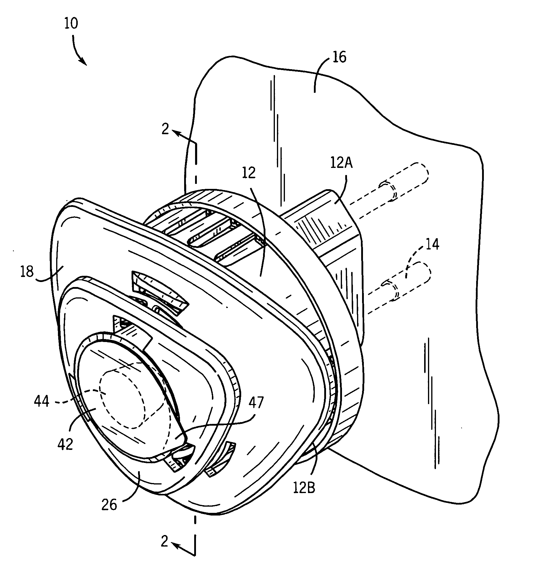
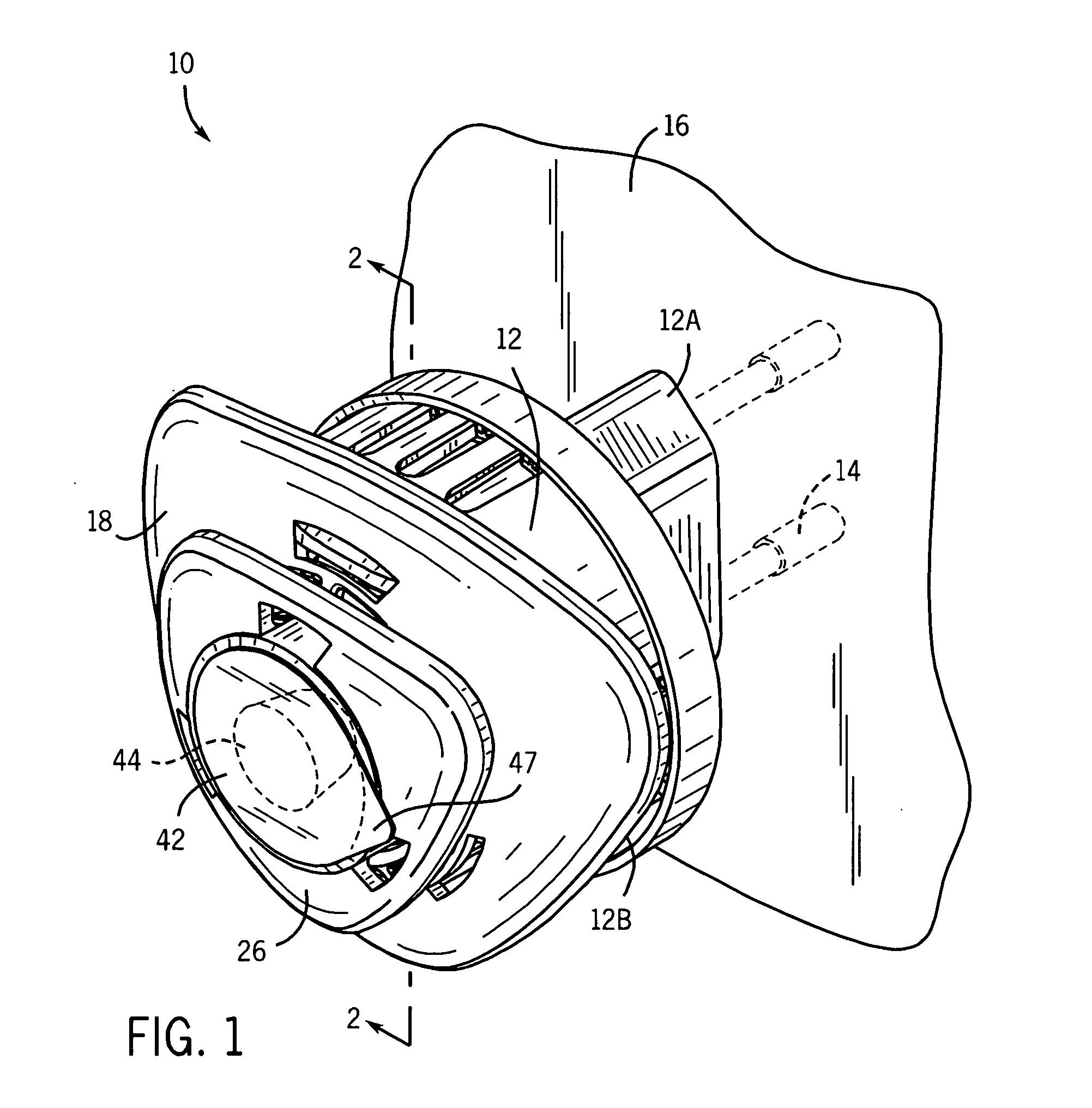
[0028] Referring first to FIG. 1, an air treatment device 10 has an outer housing 12 comprising a rear portion 12A and a frontal portion 12B. An electrical prong structure 14 is positioned in the housing 12, in the rear portion 12A, and has a rearward end extending rearwardly outwardly there from.

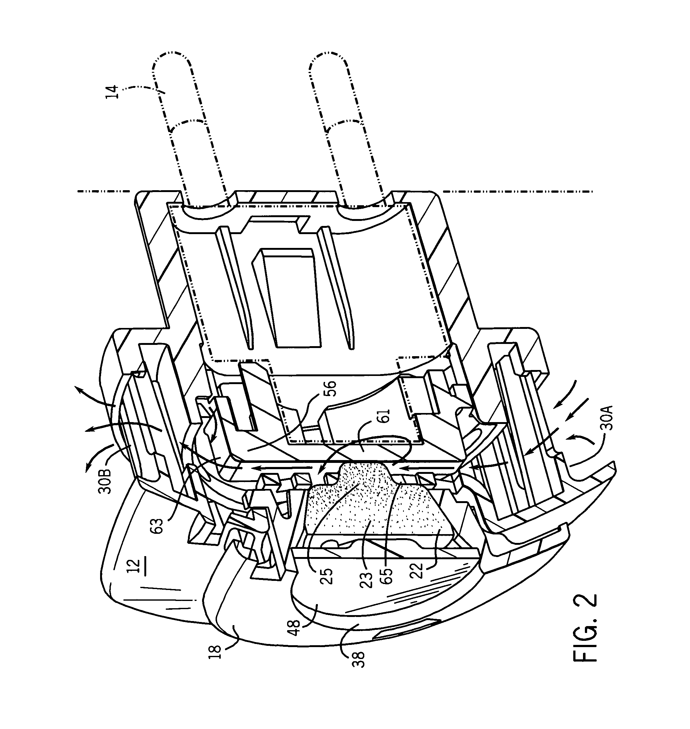
[0029] There is also a cover unit 18 mounted to the frontal housing portion 12B. The cover unit 18 mounts a substrate 22 (see especially FIG. 2) such that the substrate is essentially outwardly frontally covered, but is open towards the interior of the housing.

[0030] In a particularly preferred version there is a separately installable indicator unit 26 removably mountable to the cover unit 18 so as to project outwardly and forwardly. The indicator unit 26 is preferably removable from the cover unit 18, and houses a separate indicator chemical in a cup-shaped structure 44, which may indicate to a user the amount of air treatment chemical remaining in the substrate 22. The indicator unit 2...


PUM


Abstract

Disclosed is a device suitable for dispensing air treatment chemicals by heating a substrate impregnated with the chemicals. The device has a heater in the form of a table where a face of the table radiates heat directly to the impregnated substrate. The substrate releases the air treatment chemical back towards the heater. A transverse air pathway permits venting of the volatile chemical. Also disclosed are methods for assembling such devices.

Description

CROSS-REFERENCE TO RELATED APPLICATIONS [0001] Not applicable. STATEMENT REGARDING FEDERALLY SPONSORED RESEARCH / DEVELOPMENT [0002] Not applicable BACKGROUND OF THE INVENTION [0003] The present invention relates to devices that dispense a volatile air treatment chemical by heating a substrate that is impregnated with, or coated with, the chemical. More particularly it relates to such devices that efficiently use heat and are easily assembled. [0004] Substrates (particularly porous substrates) have previously been used as carriers for air treatment chemicals such as insect control agents (insecticides, insect repellents, insect growth regulators, attractants, synergists, etc.), fragrances and deodorizers. See e.g. U.S. Pat. No. 6,551,560. The disclosure of this patent, and of all other patents referred to herein are incorporated by reference as if fully set forth herein. [0005] Upon heating of the substrate a volatile air treatment chemical is caused to be dispensed from the substrate...

Claims


Application Information

Patent Timeline
IPC IPC(8): A24F25/00A61L9/04B05B1/24
CPCA61L9/03A01M1/2061A61L2209/135
Inventor DAVIS, BRIAN T.ADAIR, JOEL E.SALEH, SALEH A.EMMRICH, ROBERT R.
Owner DAVIS BRIAN T
Why Eureka
Try Eureka