Centrifugal Fan

a centrifugal fan and fan body technology, applied in the direction of positive displacement liquid engine, piston pump, liquid fuel engine, etc., can solve the problems of difficult to make the circuit board smaller, difficult to arrange the entire circuit board radially inside the cup-shaped portion, etc., to achieve the effect of discharging air

Active Publication Date: 2007-08-23
NIPPON DENSAN CORP
View PDF8 Cites 42 Cited by
  • Summary
  • Abstract
  • Description
  • Claims
  • Application Information

AI Technical Summary

Benefits of technology

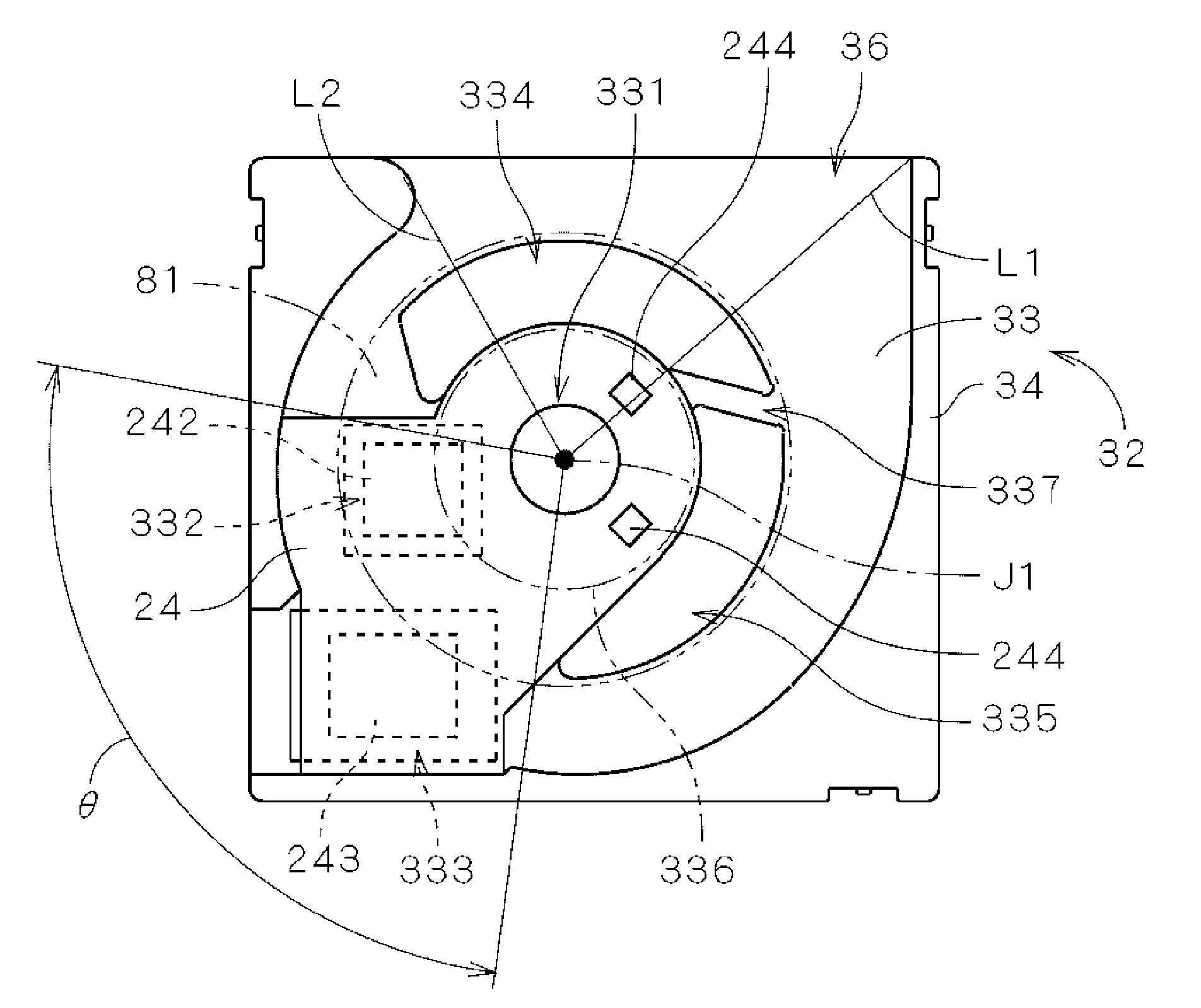
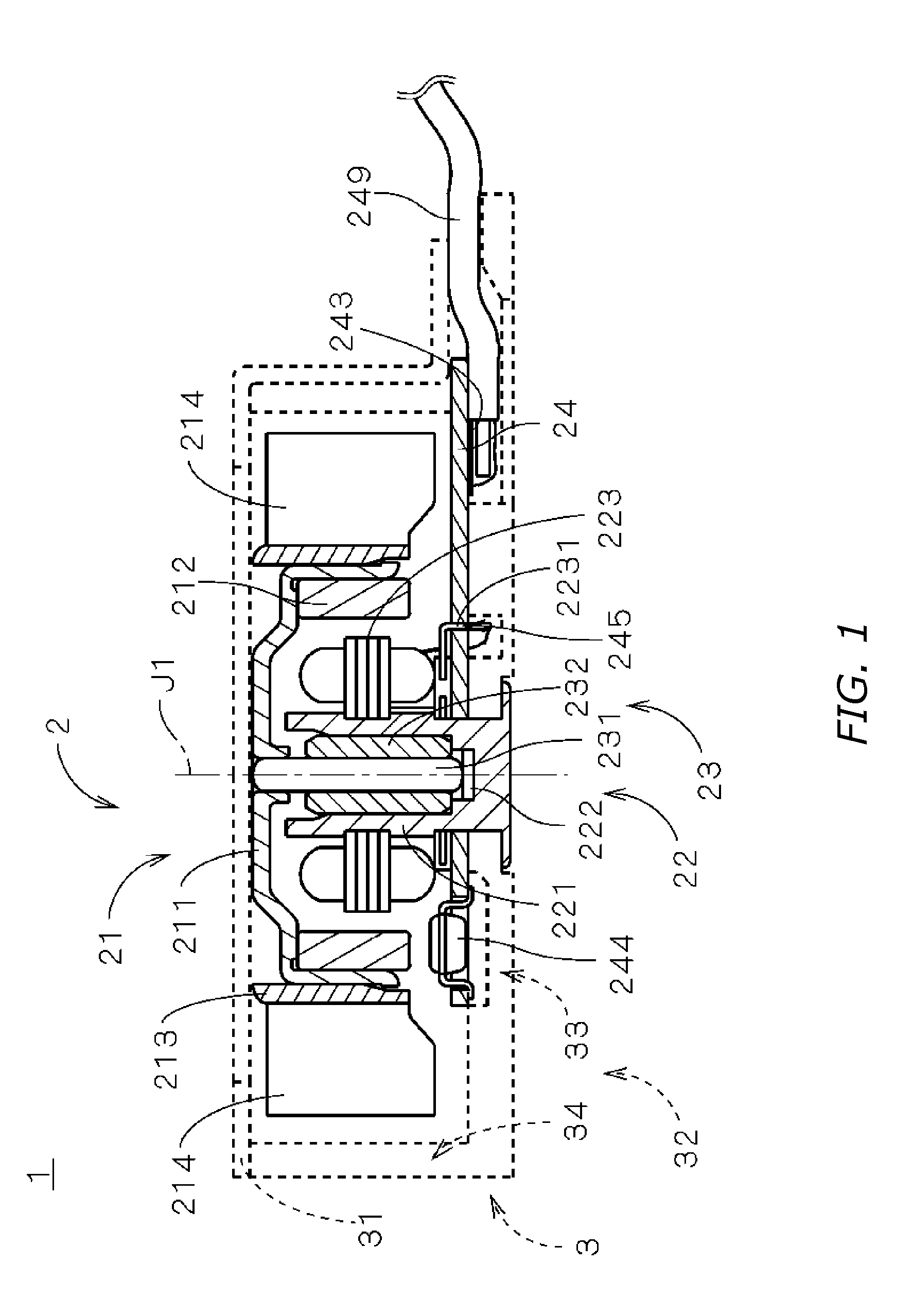
[0011]According to preferred embodiments of the present invention, a centrifugal fan having the following structure is provided. A shaft of the centrifugal fan is rotatable around a rotation axis. A cup-shaped portion is open downward and attached to the shaft. A plurality of blades are arranged outside the cup-shaped portion in a radial direction perpendicular to the rotation axis, and rotate together with the shaft and generating an airflow. A magnet and an armature, both arranged within an opening of the cup-shaped portion, generates a torque for rotating the shaft, the cup-shaped portion, and the blades. A housing, having top and bottom faces axially opposed to each other and a side face, accommodates the shaft, the cut-shaped portion, the blades, the torque generating means, and the circuit board. The bottom face of the housing has an air inlet for taking an air into the housing. The side face of the housing has an air outlet

Problems solved by technology

There is, however, a technical limitation on size reduction of electronic parts to be mounted on the circuit board.
That is, even if the size of the cup-shaped portion is reduced, it is difficult to make the circuit board smaller than an outer profile of the cup-shaped portion, which approximately corresponds to an area of the opening of the cup-shaped portion, when the circuit board and the cup-shaped portion are seen in the axial direction.
Therefore, it is difficult to arrange the entire circuit board radially inside the cup-shaped portion so as not to interfere with the air inlet opposed to the blades of the impeller as proposed in JP '756.
This causes various problems, for example, degradation of the air-blowin

Method used


Image

  • Centrifugal Fan
  • Centrifugal Fan
  • Centrifugal Fan

Examples


Embodiment Construction

[0030]Referring to FIGS. 1 through 16, preferred embodiments of the present invention will be described in detail. It should be noted that in the explanation of the present invention, when positional relationships among and orientations of the different components are described as being up / down or left / right, ultimate positional relationships and orientations that are in the drawings are indicated; positional relationships among and orientations of the components once having been assembled into an actual device are not indicated. Meanwhile, in the following description, an axial direction indicates a direction parallel to a rotation axis, and a radial direction indicates a direction perpendicular to the rotation axis.

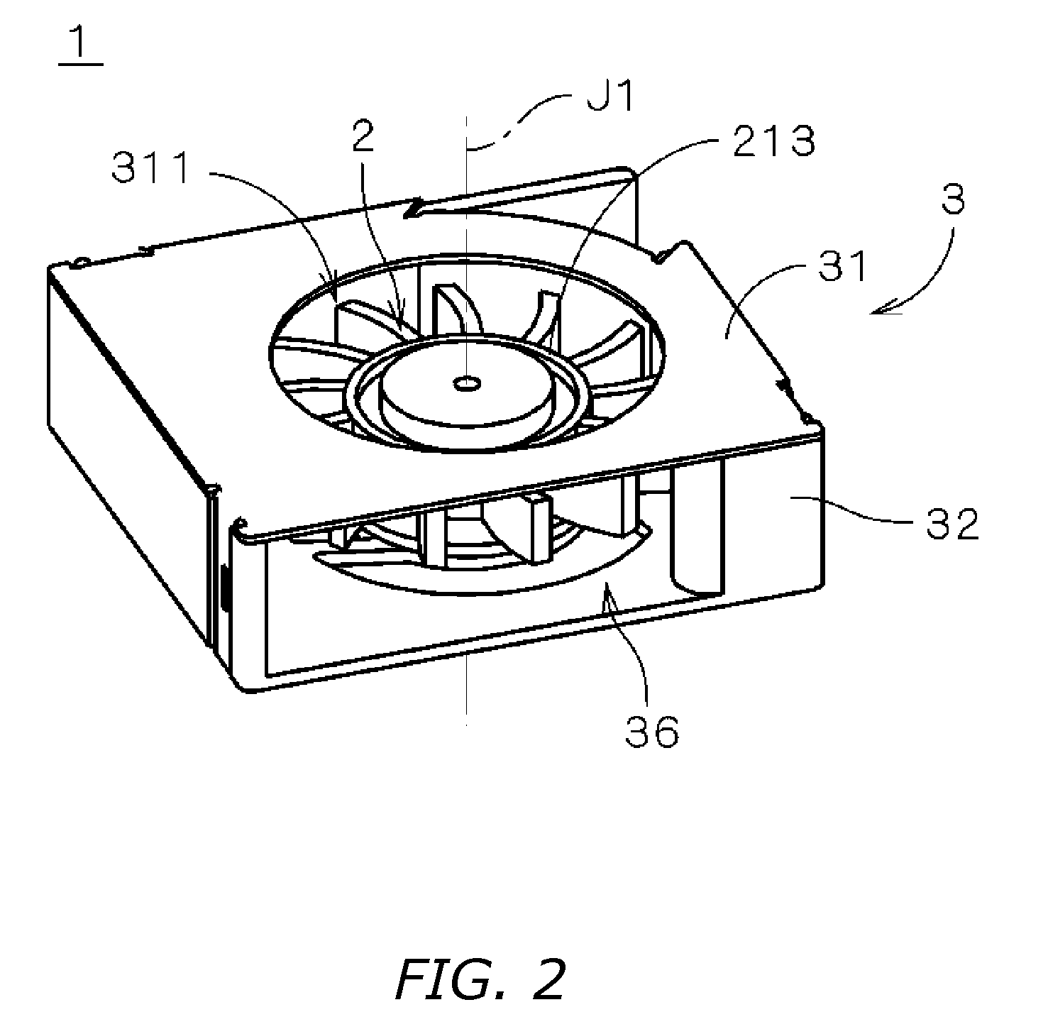
[0031]FIG. 1 is a vertical cross-sectional view of a compact centrifugal fan 1 according to a preferred embodiment of the present invention. FIG. 2 is a perspective view showing an appearance of the centrifugal fan 1. FIG. 3 is a perspective view of the centrifugal fan ...


PUM


Abstract

An arrangement of a low air inlet and a circuit for driving a torque generator in an ultra-compact centrifugal fan is disclosed. In the ultra-compact centrifugal fan, a region occupied by the circuit is not completely arranged radially inside a cup-shaped portion to which an impeller is attached. At least a part of the low air inlet provided on a bottom of a housing of the centrifugal fan is arranged in a range of predetermined angle in an imaginary ring-shaped portion surrounding a base portion covered by the cup-shaped portion. A part of the circuit, that is not covered by the cup-shaped portion, is arranged upstream of the range of the predetermined angle in a flowing direction of airflow.

Description

BACKGROUND OF THE INVENTION[0001]1. Technical Field[0002]The present invention relates to a centrifugal fan used for blowing air.[0003]2. Description of the Related Art[0004]There are known centrifugal fans that inhale air in an axial direction parallel to a rotation axis and exhale air in a radial direction perpendicular to the axial direction. The centrifugal fans include an impeller having a plurality of blades circumferentially arranged around the rotation axis and accommodated in a housing.[0005]Japanese Unexamined Patent Publication No. 7-111756 (hereinafter, referred to as JP '756) describes air inlets provided on both sides of the housing in the axial direction of the centrifugal fan (i.e., inhaling air from both sides of the housing). This technique increases a flow rate in the centrifugal fan. In the centrifugal fan of JP '756, a cup-shaped portion having an opening is arranged in the housing to be open downward. A magnet for producing a magnetic field is arranged on an in...

Claims


Application Information

Patent Timeline
IPC IPC(8): H02K9/00H02K7/00H02K11/00
CPCF04D25/0613F04D25/08F04D29/424H01L23/467H01L2924/0002H01L2924/00
Inventor TESHIMA, HIROYOSHITAKESHITA, KAZUMINAGAMATSU, HIDEKIKONISHI, HIDEAKITAKAOKA, TSUKASAIDA, KIYOTO
Owner NIPPON DENSAN CORP
Why Eureka
Try Eureka