Electronic article surveillance marker

a technology of electronic articles and surveillance markers, which is applied in the direction of burglar alarms by hand-portable articles removal, burglar alarm mechanical actuation, etc., can solve the problems of harmonic system superposition, harmonic system is also known to be vulnerable to false alarms, and harmonic system encounters a number of problems, so as to improve the production yield of markers and the reliability of eas operation, the effect of easy and reliable production and large footprin

Inactive Publication Date: 2007-08-23
PHENIX LABEL
View PDF19 Cites 18 Cited by
  • Summary
  • Abstract
  • Description
  • Claims
  • Application Information

AI Technical Summary

Benefits of technology

The invention relates to a method for producing markers that can be used in electronic article surveillance (EAS) systems. By measuring the resonant frequencies of markers made from unannealed magnetostrictive material, the method allows for better frequency allocation and higher yields of usable markers. This results in improved efficiency and reliability of EAS operations. Additionally, this method enables the creation of small, reliable markers with multiple layers of unannased material, making them easier and more cost-effective to produce compared to previous options.

Problems solved by technology

The technical problem addressed in this patent text is the need for a more effective EAS marker that can be used in a retail environment. Current markers have large size and can be difficult to detect and may also produce false alarms. The patent describes various improvements to the marker and the detection system, but acknowledges that there are still issues with size and reliability. The patent proposes a solution to the problem by introducing a new marker design that addresses the issues with size and detection.

Method used


Image

  • Electronic article surveillance marker
  • Electronic article surveillance marker
  • Electronic article surveillance marker

Examples


example 1

Short Duration Marker Production and Testing

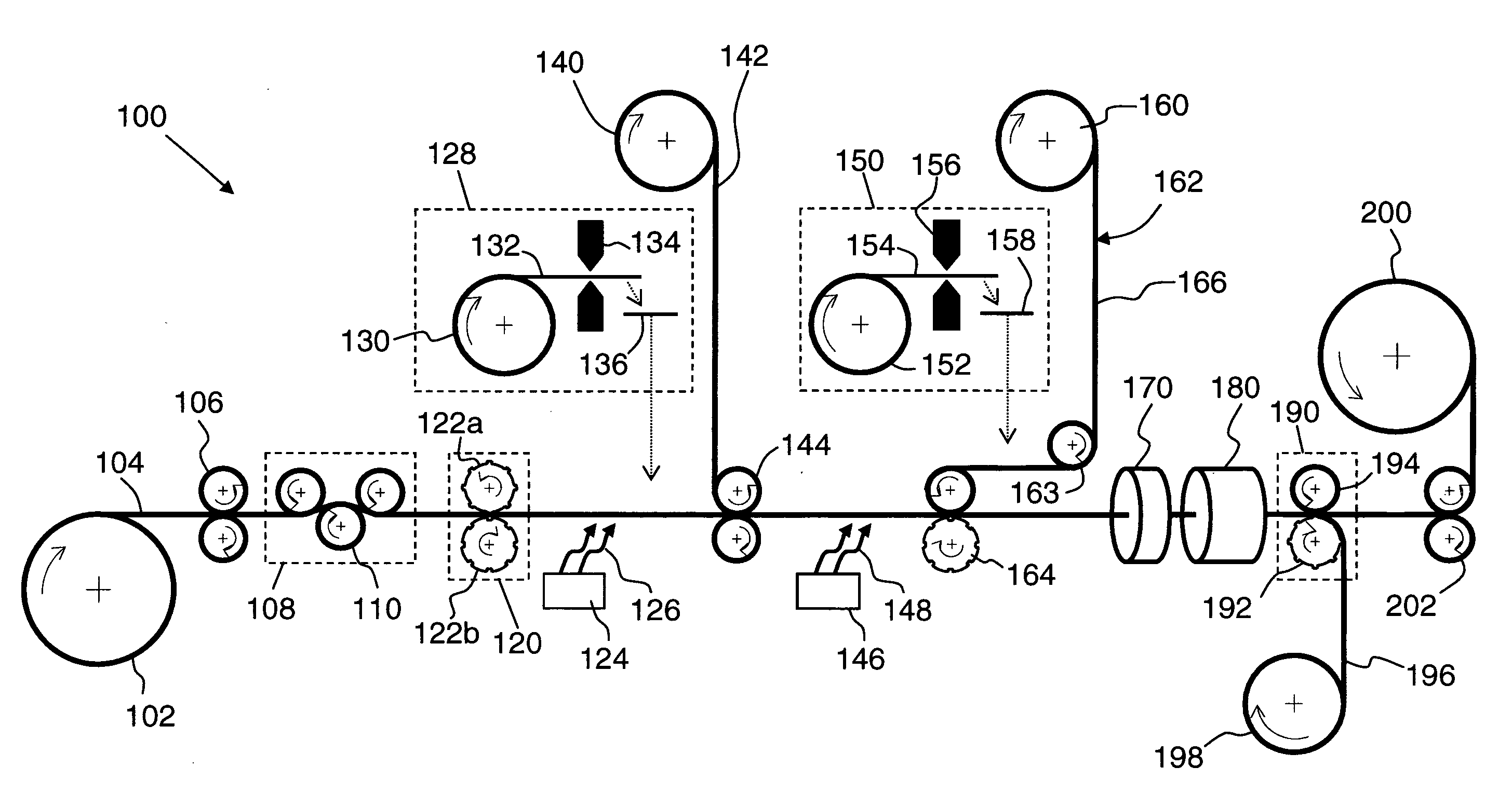
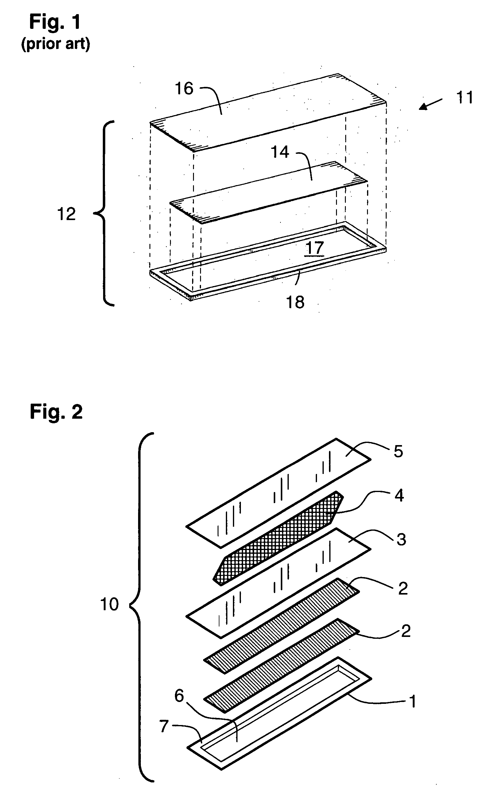
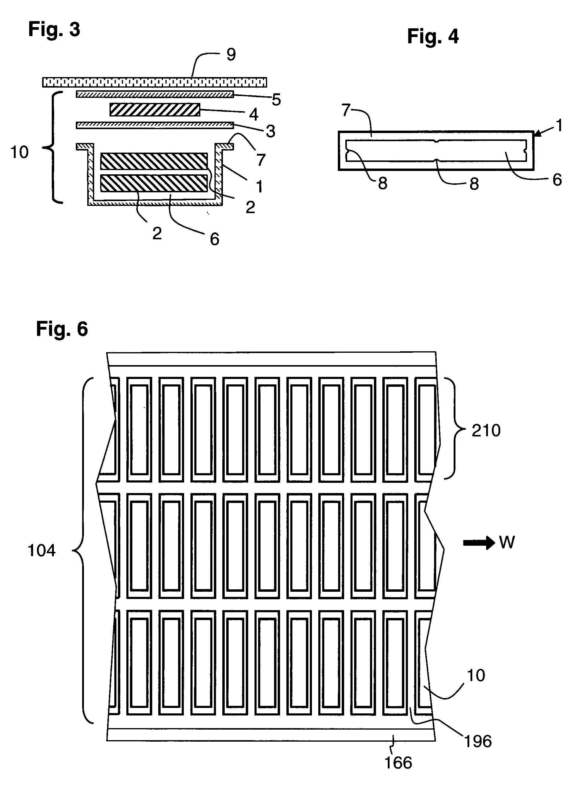
[0066]A series of magnetomechanical EAS labels having a natural resonant frequency for magnetomechanical oscillation are produced using a continuous-feed, web-based press. Each label comprises a housing having a cavity, two resonator strips disposed in the cavity to form a magnetomechanical element, and a bias magnet adjacent the resonator strips. The production is accomplished using a press adapted to carry out, in sequence, the following steps: (i) embossing cavities in a high-impact polystyrene-polyethylene laminate webstock material; (ii) cutting magnetostrictive amorphous metal ribbon stock to form resonator strips having a preselected resonator strip length; (iii) placing two of the resonator strips in each cavity; (iv) covering and sealing each cavity with a lidstock material that confines the resonator strips in the cavity without constraining their ability to vibrate mechanically; (v) cutting semi-hard magnetic material to form bi...

example 2

Extended Duration Marker Production and Testing

[0070]The efficacy of the adaptive feedback label production system used for the experiments of Example 1 is tested during extended duration production. The system is operated in a normal factory production schedule to produce labels using the same nominal resonator and bias materials employed in Example 1. However, multiple supply lots are used over several days' worth of production. The press is operated for several days each without and with use of the adaptive resonator strip length control. Results are set forth in Table II below.

TABLE IIProduction Statistics For EAS Label FabricationfeedbackaveragestandardRunmodefrequencydeviationNo.(on / off)(Hz)(Hz)A1off58096634B1off58087733A2on58067273B2on58055336

[0071]Although Runs A1 and B1 both achieve an average resonant frequency close to the desired 58050 Hz value, the standard deviation over the production run of over 1,000,000 markers is substantially larger than the standard deviations a...


PUM

PropertyMeasurementUnit
Lengthaaaaaaaaaa
Lengthaaaaaaaaaa
Lengthaaaaaaaaaa

Abstract

A fabrication process produces markers for a magnetomechanical electronic article surveillance system. The marker includes a magnetomechanical element comprising one or more resonator strips of magnetostrictive amorphous metal alloy; a housing having a cavity sized and shaped to accommodate the resonator strips for free mechanical vibration therewithin; and a bias magnet to magnetically bias the magnetomechanical element. The process employs adaptive control of the cut length of the resonator strips, correction of the length being based on the deviation of the actual marker resonant frequency from a preselected, target marker frequency. Use of adaptive, feedback control advantageously results in a much tighter distribution of actual resonant frequencies. Also provided is a web-fed press for continuously producing such markers with adaptive control of the resonator strip length.

Description


Claims


Application Information

Patent Timeline
Owner PHENIX LABEL
Why Eureka
Try Eureka