
Image-providing apparatus, image-printing apparatus and image-printing system comprised thereof

Inactive Publication Date: 2007-08-23
CANON KK
View PDF21 Cites 29 Cited by
  • Summary
  • Abstract
  • Description
  • Claims
  • Application Information

AI Technical Summary

Benefits of technology

[0015] The present invention is conceived in light of the problems of the conventional art as described above, and has as its main object to provide an image-providing apparatus, an image-printing apparatus and an image-printing system comprised thereof that is capable of providing a cooperative capability separate from the standardized capabilities while improving user operability.

Problems solved by technology

However, for those settings that are not specified by standard, in carrying out these settings and the processes based on them, such as print adjustment and correction, the following problems arise:
As a result, until such time as the standard itself is upgraded to a new version or the desired print adjustment and correction functions are themselves standardized, any print adjustment or correction function that cannot be implemented with an extension within the restricted range can only be provided as an incompatible proprietary function.
Even when implementing desired print adjustment and correction functions that are incompatible with the standard by using vendor-specific methods, since uniform standard support is required it is ultimately necessary to deal with two sets of procedures, which does not facilitate efficient development.
In any case, however, the user is required to use both the printer user interface (UI) and the DSC UI, or the PC application UI and the DSC UI, and to configure two apparatuses, which complicates operation.
Moreover, since it is not possible to check all configuration setting contents with just the DSC UI alone, ultimately it is necessary to check both UI repeatedly prior to printing.

Method used


Image

  • Image-providing apparatus, image-printing apparatus and image-printing system comprised thereof
  • Image-providing apparatus, image-printing apparatus and image-printing system comprised thereof
  • Image-providing apparatus, image-printing apparatus and image-printing system comprised thereof

Examples


first embodiment

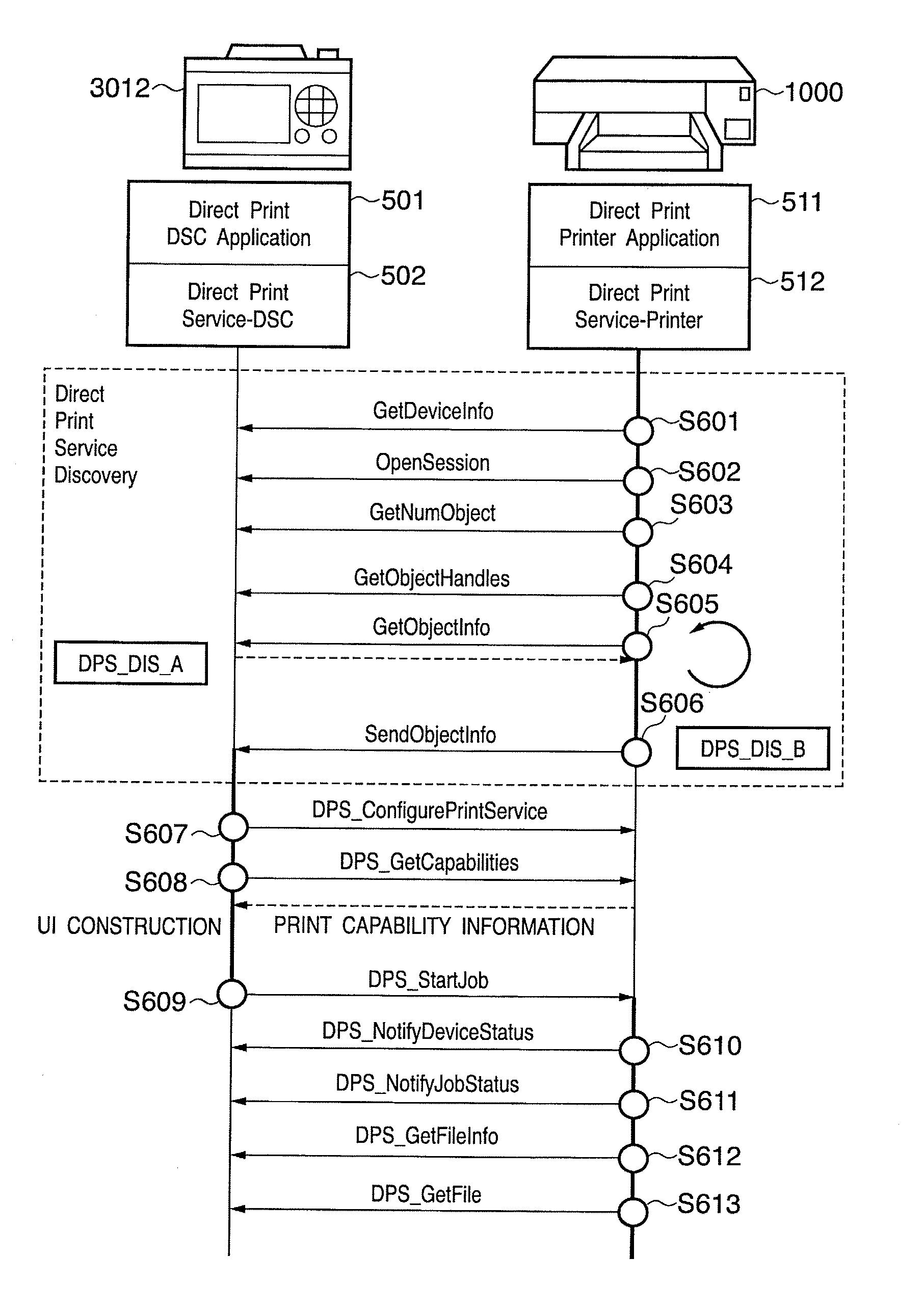
[0122]FIG. 8 is a diagram illustrating the protocol stacks of the control programs of the DSC 3012 and the PD printer 1000 according to a first embodiment of the present invention. In FIG. 8 the same reference numerals are used for the same stacks shown in FIG. 5, and descriptions thereof are omitted.

[0123] As is clear from a comparison of FIG. 5 and FIG. 8, in the present embodiment, the protocol stacks 801, 802, 811, 812 according to the default settings are added as the top layers of the PTP protocol layer.

[0124] Default Setting Service-DSC 802 is a default setting protocol layer that uses the lower-layer PTP-Responder file transfer function to implement the default setting function.

[0125] Default Setting DSC Application 801 is a default setting application layer that forms the actual digital camera 3012 side in the default setting system using the lower-layer default setting function as well as the group of buttons and switches 34, the LCD 35, the connector 39, the storage me...

second embodiment

[0243] Next, a description is given of a second embodiment of the present invention.

[0244] In the present embodiment, the script file relating to DSS that is transmitted from the PD printer 1000 to the DSC 3012 is the same as that of the first embodiment except for the operation of constructing the UI at the DSC 3012, and therefore a description of the same structures and operations is omitted.

[0245]FIG. 12 is a diagram showing an example of the “DSS_DIS_B” default setting supported notification script transmitted in step S952 shown in FIG. 9 from the PD printer 1000 that is one example of an image-printing apparatus according to the present embodiment.

[0246] SC1201 is a tag showing the start of a first supported function description. In the present embodiment, this tag can be used multiple times, enabling the relations between the respective print modes options and the other adjustments and corrections to be defined.

[0247] SC1202 is a tag showing the start of description of sup...


PUM


Abstract

A procedure that confirms the presence or absence of support for standardized capabilities is present in transmissions to an image-providing apparatus having a photo-direct print capability and an image-printing apparatus, for example. The procedure is used to exchange information relating to the presence or absence of support for a service that provides a cooperative capability separate from the standardized capabilities, making it possible to use non-standard capabilities while maintaining compatibility with devices that do not support the service that provides the cooperative capability separate from the standardized capabilities.

Description

BACKGROUND OF THE INVENTION [0001] 1. Field of the Invention [0002] The present invention relates to an image-providing apparatus that communicates directly with an image-printing apparatus, an image-printing apparatus that communicates with an image-providing apparatus, and further, an image-printing system created by communication between an image-providing apparatus and an image-printing apparatus. [0003] 2. Description of the Related Art [0004] When printing an image captured with a digital camera, the typical procedure involves scanning the image to be printed into a personal computer (hereinafter “PC”) and printing it with a printer that is connected to the PC using an application running on the PC. [0005] It should be noted that, in this specification, devices that are provided with the capability to record a captured image in digital data format are collectively called digital cameras (“DSC”). Therefore, a digital video camera that has a still-image capture function is of co...

Claims


Application Information

Patent Timeline
IPC IPC(8): G06F3/12
CPCH04N1/00278H04N1/33315H04N1/33376H04N2201/0084H04N2201/0041H04N2201/0049H04N2101/00
Inventor YAMADA, AKITOSHIKATO, MASAOHORIUCHI, AKINORISASAKI, FUTOSHIGYOTOKU, TAKASHI
Owner CANON KK
Learn More