Endoscope device and imaging method using the same

a technology of endoscope and imaging method, which is applied in the field of endoscope devices, can solve the problems that the conventional endoscope cannot perform image capturing that satisfies the demands of the observer, and achieve the effect of appropriately performing image capturing over a wide rang

Inactive Publication Date: 2007-08-23
CONOPCO INC D B A UNILEVER +1
View PDF0 Cites 153 Cited by
  • Summary
  • Abstract
  • Description
  • Claims
  • Application Information

AI Technical Summary

Benefits of technology

[0037] According to the present invention, it is possible to provide an endoscope device a

Problems solved by technology

That is, the conventional endoscope cannot perform i

Method used


Image

  • Endoscope device and imaging method using the same
  • Endoscope device and imaging method using the same
  • Endoscope device and imaging method using the same

Examples


Embodiment Construction

[0058] An endoscope device according to an embodiment of the present invention will be explained below with reference to the drawings.

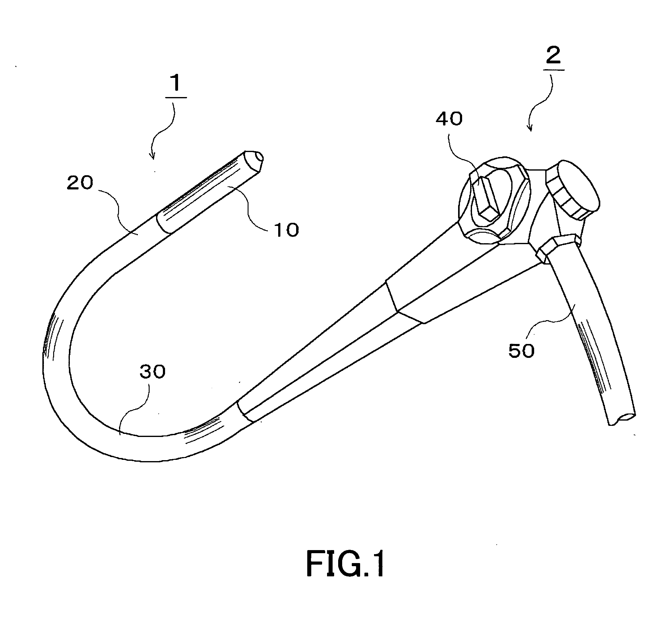
[0059]FIG. 1 is a perspective diagram showing the appearance of an endoscope device to be applied to the embodiment of the present invention. As shown, the endoscope device comprises an inserting unit 1, which is elongate and flexible, and an operation unit 2.

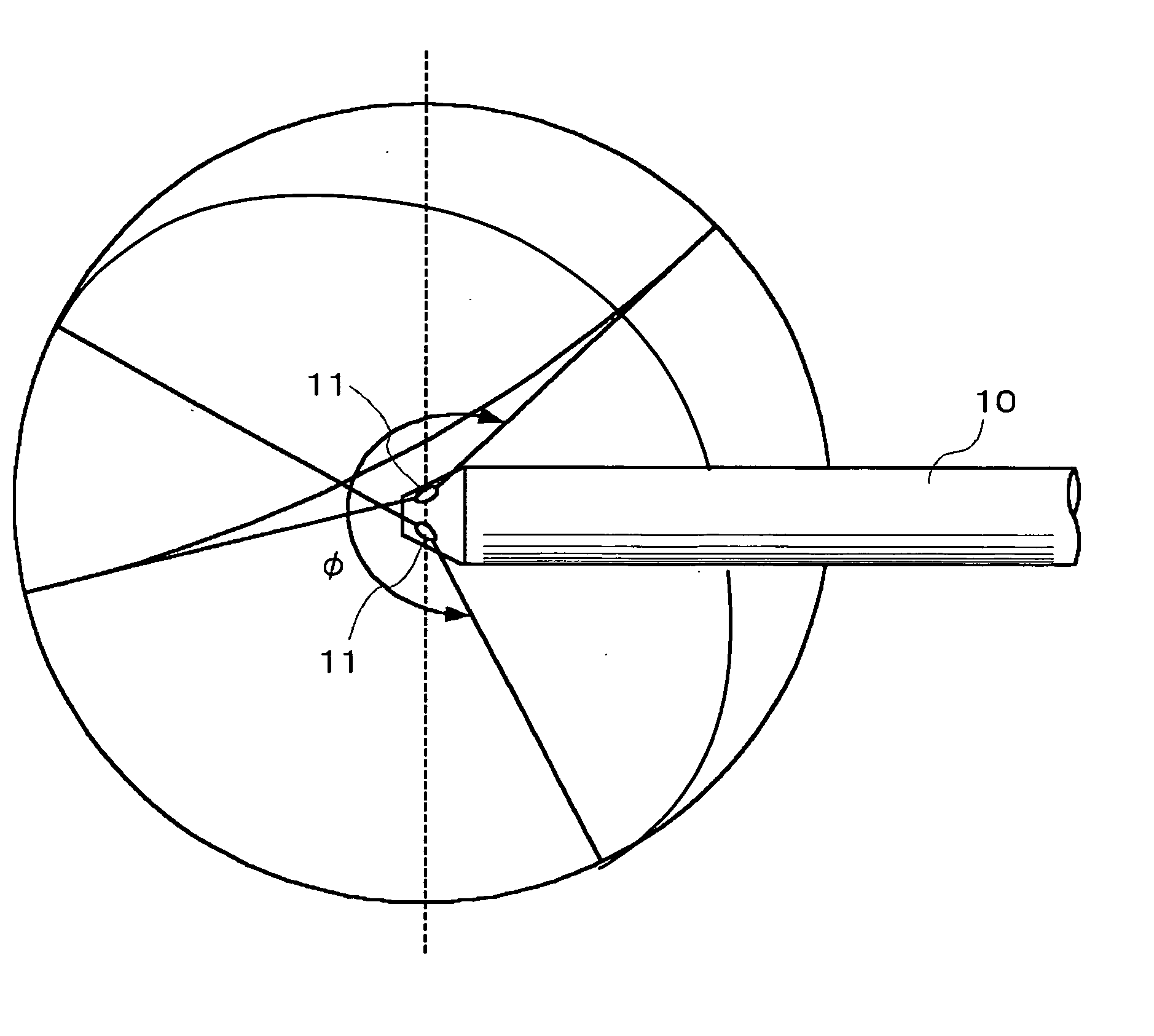
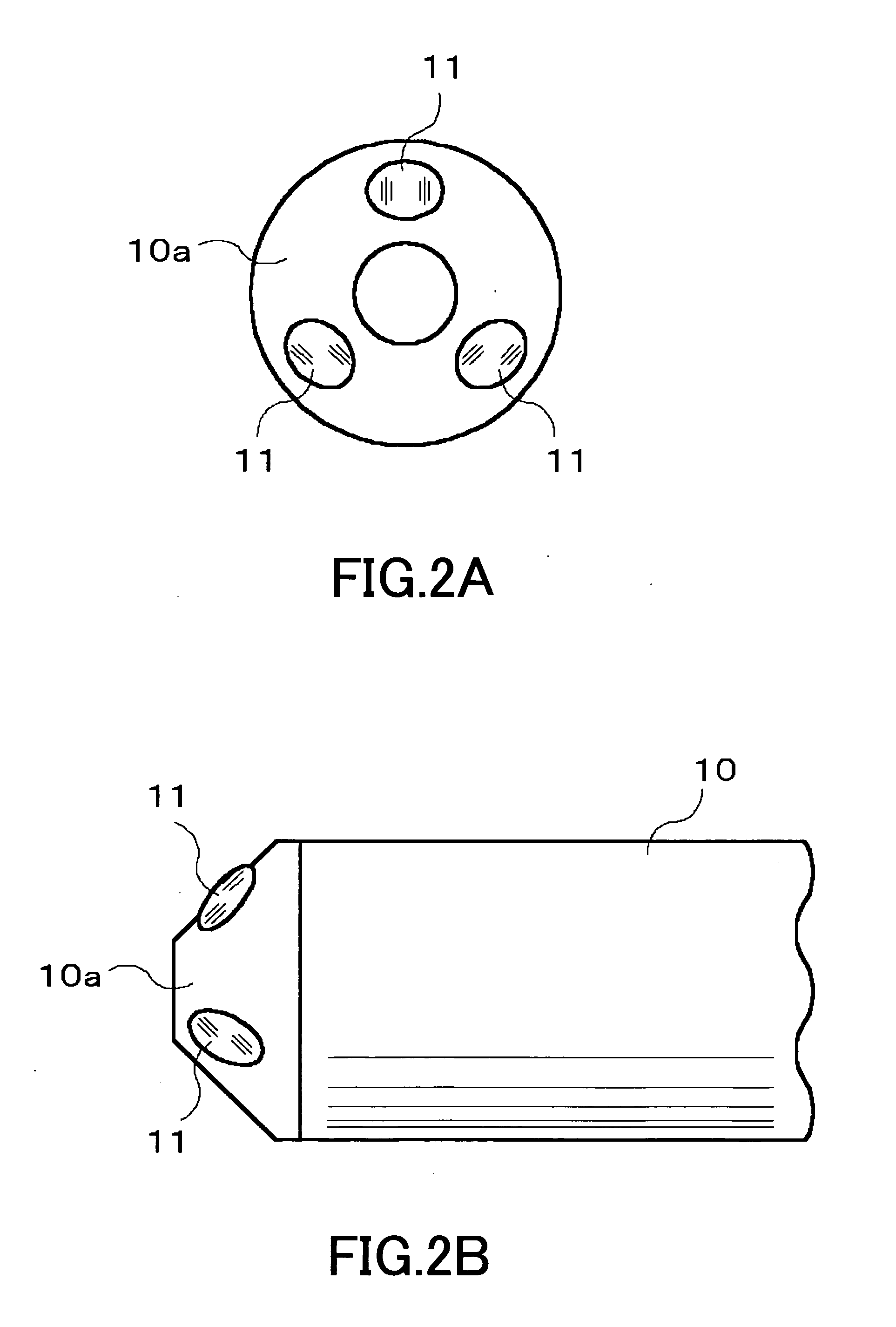
[0060] The inserting unit 1 comprises a head portion 10 in which a plurality of optical systems are disposed, a curving portion 20 free to curve formed of jointed curve pieces, and a limber flexible tubular portion 30 adjoining the curving portion 20 and having flexibility.

[0061] The operation unit 2 comprises an operation knob 40 and a cable 50.

[0062] The operation knob 40 is connected to the curving portion 20 by a known drive mechanism, can curve the curving portion 20 to an arbitrary direction in response to a rotation (turn) of the operation knob 40.

[0063] The cable 50 is detachably con...


PUM


Abstract

Three objective lenses (11) having optical axes L oriented to different directions are mounted on a head portion (10) of an endoscope device. The objective lens (11) has a predetermined view angle θ centered by the optical axes L. Each objective lens (11) is disposed so as to have the peripheral portions of its viewing field overlap with the peripheral portions of the viewing fields of adjoining other objective lenses (11). Hence, the three objective lenses (11) causes the head portion (10) as a whole to have a view angle φ extending over a wider range than the view angle θ of the objective lens (11) with no discontinuation. Each optical image of a testing target part captured within this view angle φ is imaged by an imaging element.

Description

TECHNICAL FIELD [0001] The present invention relates to an endoscope device for medical or industrial use, and an imaging method using the same. BACKGROUND ART [0002] Conventionally, a medical endoscope for capturing images inside a body cavity by inserting an elongate inserting unit into the body cavity (lumen) has been widely used. [0003] For example, as shown in FIG. 7, such an endoscope has an objective lens 110 at the head of its inserting unit 100. The objective lens 110 has an optical axis L defined in the longer axis direction, and catches the testing target part (observation part) ahead, in a predetermined view angle (for example, about 140 degrees) fanning out about the optical axis L. An optical image of the testing target part caught by the objective lens is formed on an imaging element such as a CCD (Charge Coupled Device), etc. via an unillustrated internally disposed lens mechanism (relay optical system, etc.). [0004] That is, when the inserting unit 100 as shown in F...

Claims


Application Information

Patent Timeline
IPC IPC(8): A61B1/06A61B1/04
CPCA61B1/00096A61B1/04A61B1/00181A61B1/00179
Inventor OSAKA, SHOJI
Owner CONOPCO INC D B A UNILEVER
Why Eureka
Try Eureka