Permanent magnet embedment rotating electric machine, motor for car air conditioner, and enclosed electric compressor

a technology of permanent magnet and rotating electric machine, which is applied in the direction of magnetic circuit rotating parts, dynamo-electric machines, magnetic circuit shape/form/construction, etc., can solve the problems of vibration and noise in the rotating electric machine, and the prevention of torque pulsation becomes difficult, so as to suppress torque pulsation, prevent torque pulsation, and torque ripple

Inactive Publication Date: 2007-08-30
TOYOTA IND CORP
View PDF9 Cites 27 Cited by
  • Summary
  • Abstract
  • Description
  • Claims
  • Application Information

AI Technical Summary

Benefits of technology

[0008]An objective of the present invention is to provide a permanent magnetic embedment rotating electric machine capable of preventing decreases in torque, and further of suppressing torque pulsation, torque ripple, i.e., degree of fluctuation width of output torque.

Problems solved by technology

Since sudden magnetic flux density fluctuation occurs at a location (magnetic pole switching part) between the two adjacent permanent magnets, torque pulsation occurs and causes vibration and noise in the rotating electric machine.
Thus, the prevention of torque pulsation becomes difficult.

Method used


Image

  • Permanent magnet embedment rotating electric machine, motor for car air conditioner, and enclosed electric compressor
  • Permanent magnet embedment rotating electric machine, motor for car air conditioner, and enclosed electric compressor
  • Permanent magnet embedment rotating electric machine, motor for car air conditioner, and enclosed electric compressor

Examples


Embodiment Construction

[0039]A first embodiment of the present invention will now be described with reference to FIGS. 1 to 12D.

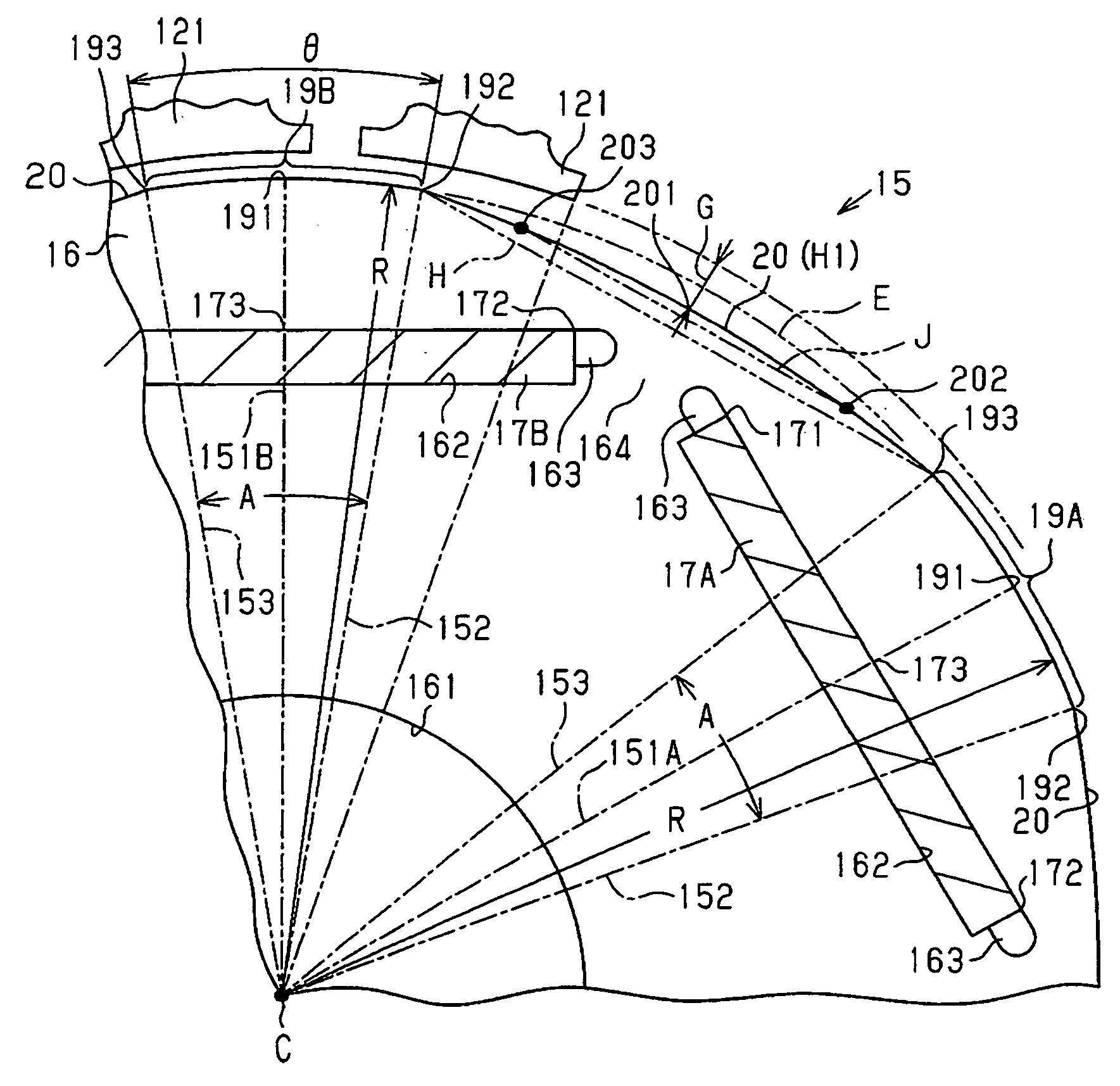
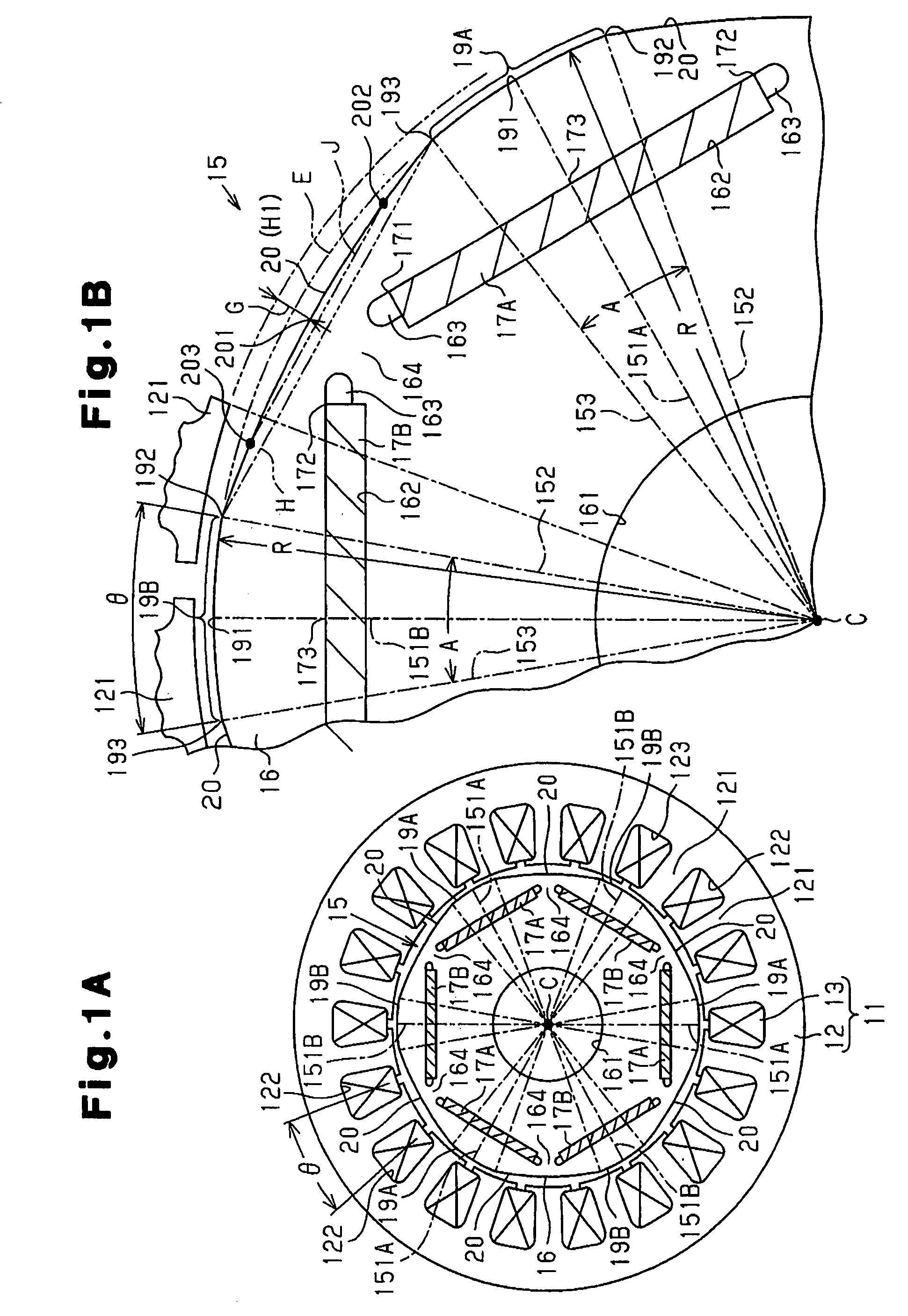
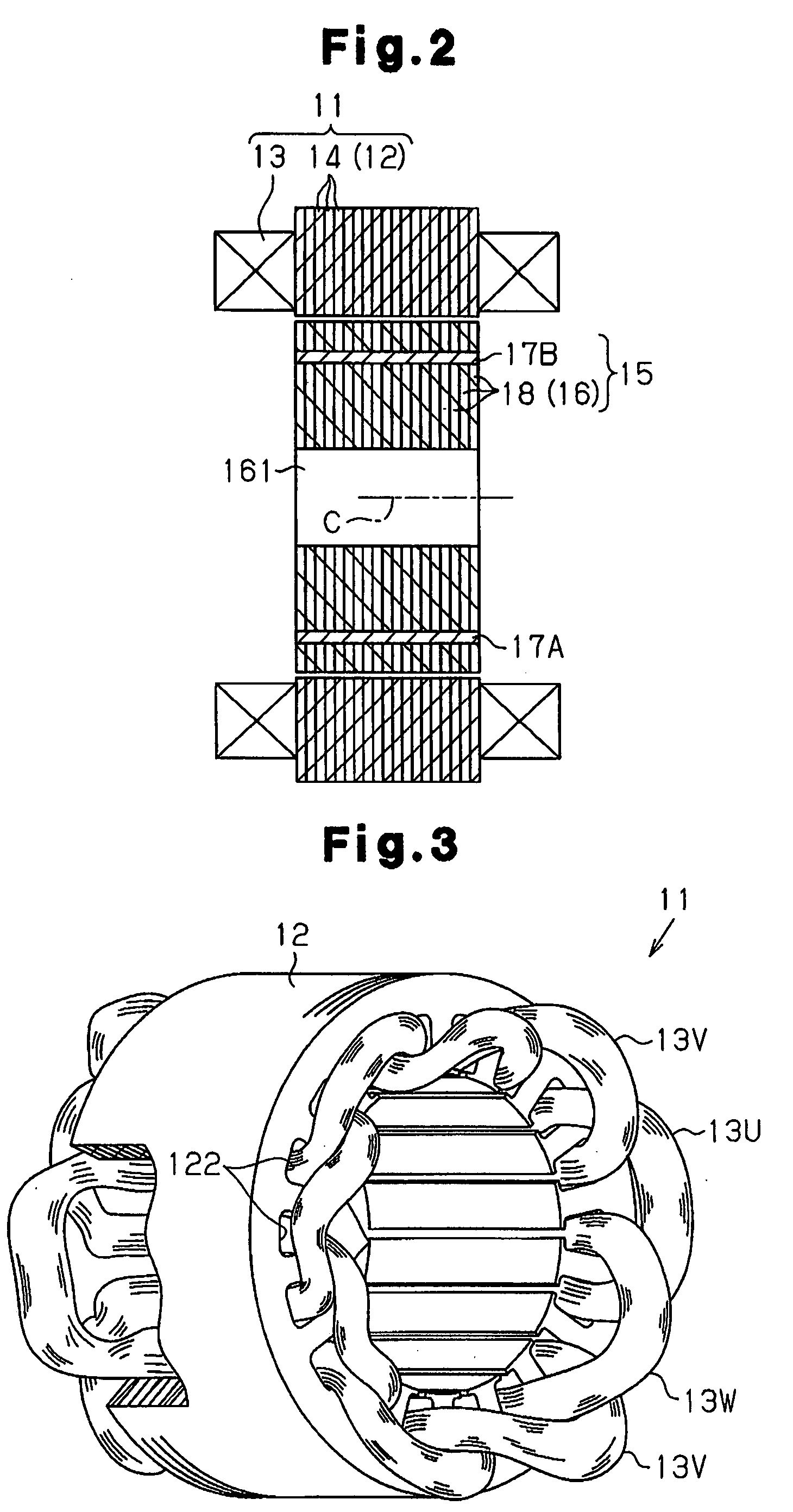
[0040]As shown in FIG. 1A, a stator 11 includes an annular stator core 12 and a coil 13 arranged in slots 122 formed between a plurality of teeth 121 arranged along the inner periphery of the stator core 12. In the present embodiment, the quantities of the teeth 121 and slots 122 are each eighteen. The slots 122 are arranged at an equal pitch (equiangular pitch) in the circumferential direction of the annular stator 11. As shown in FIG. 2, the stator core 12 is formed by stacking a plurality of core plates 14, which are magnetic bodies (steel plates). The coil 13 arranged in the slot 122 is wound into a wave winding.

[0041]Generally, the following relational equation is satisfied when expressing the number of poles as p (integer), the number of phases as m (integer), the number of slots per phase for each pole as q (every 0.5, such as q=0.5, 1, 1.5, 2, 2.5, . . . ), and the number...


PUM


Abstract

A plurality of convex portions are located inside of a virtual circumferential surface. Each convex portion connects an adjacent pair of circumferential portions with each other. Each convex portion is an arcuate curve bulging radially outward. Each convex portion defines a minimum radius. A difference between a radius R and the minimum radius is a depth Dh. Dhr=Dh×25.5 / R. A range of an angular width A in relation to circumferential portion and a range of the depth Dh are set by the following expression,(5.6×Dhr+11.3)°×6 / p≦A<35°×6 / p andA<[360 / p−2×arccos]°  (1)Therefore, decrease in torque is prevented. Torque pulsation is suppressed.

Description

BACKGROUND OF THE INVENTION[0001]The present invention relates to a permanent magnet embedment rotating electric machine in which a plurality of permanent magnets are embedded as magnetic poles inside a rotor that rotates in a stator around which windings are wound. The present invention also relates to a motor for a car air conditioner incorporating such a rotating electric machine and to an enclosed electric compressor.[0002]A plurality of permanent magnets are embedded inside the rotor of this type of rotating electric machine so as to be adjacent to each other in the circumferential direction of the rotor. Two permanent magnets adjacent to each other in the circumferential direction of the rotor are set so that the magnetic poles are differently arranged. Since sudden magnetic flux density fluctuation occurs at a location (magnetic pole switching part) between the two adjacent permanent magnets, torque pulsation occurs and causes vibration and noise in the rotating electric mach...

Claims


Application Information

Patent Timeline
Patent Type & Authority Applications(United States)
IPC IPC(8): H02K21/12H02K1/27
CPCH02K1/276H02K2213/03H02K29/03H02K1/27
Inventor ADANIYA, TAKUMERA, MINORUUETSUJI, KIYOSHISAEKI, AIKOBAYASHI, MASATOSHIFUKASAKU, HIROSHI
Owner TOYOTA IND CORP
Why Eureka
Try Eureka