Loop antenna and RFID tag
a loop antenna and rfid tag technology, applied in the field of loop antennas, can solve the problems of deteriorating efficiency in transmission and reception of electric waves, small loop antenna size, and inability to obtain high gain, and achieve the effect of high gain loop antenna and high gain rfid tag
- Summary
- Abstract
- Description
- Claims
- Application Information
AI Technical Summary
Benefits of technology
Problems solved by technology
Method used
Image

Examples
embodiment
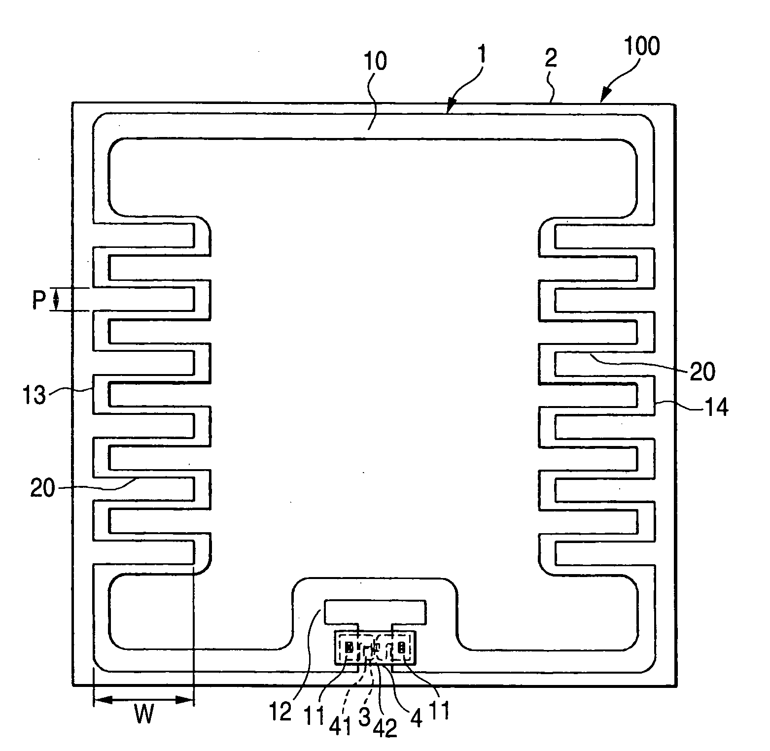
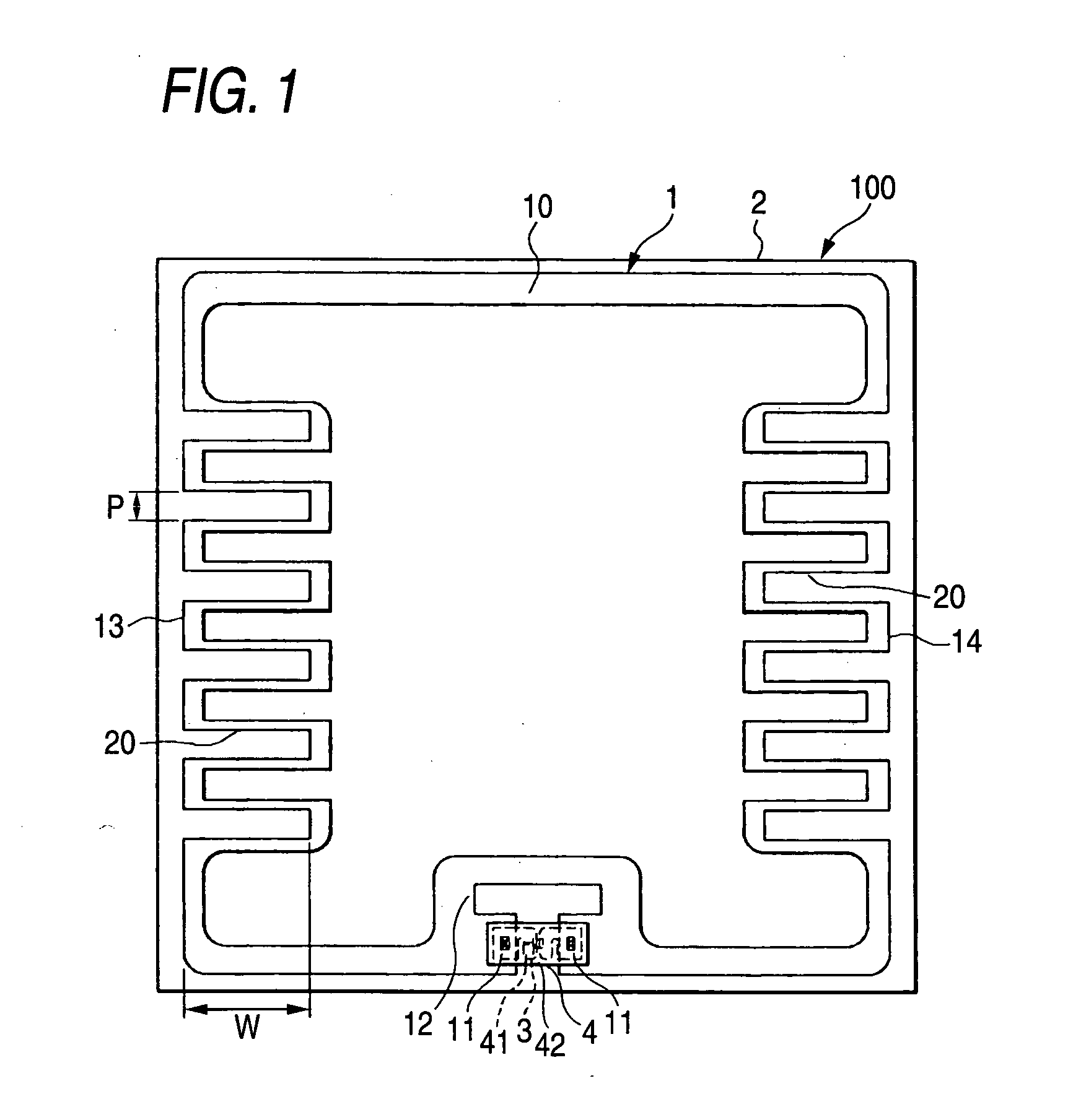
[0032]FIG. 1 is a plan view showing the configuration of an RFID tag according to this embodiment.
[0033]An RFID tag 100 includes an antenna 1, a dielectric substrate 2, an integrated circuit 3, and a strap 4. The antenna 1 includes a line member 10, power feeding parts 11, and a matching circuit 12. In addition, the line member 10 includes meandering parts 13 and 14.
[0034]The antenna 1 is used to transmit and receive an electric wave. Specifically, the antenna is a so-called loop antenna having an annular shape. The antenna may be made of any material as long as the antenna is made of conductor. In general, a filmy conductor, for example, metal is used as the antenna 1. However, the thickness of the conductor is not limited. Hereinafter, the antenna formed of aluminum that is rolled to have a thickness of about 15 μm will be described as an example of the antenna.
[0035]The line member 10 is a conductor having one or more meandering parts. For example, the line member 10 includes sid...
PUM
 Abstract
Description
Claims
Application Information
 - Generate Ideas
- Intellectual Property
- Life Sciences
- Materials
- Tech Scout
- Unparalleled Data Quality
- Higher Quality Content
- 60% Fewer Hallucinations
Browse by: Latest US Patents, China's latest patents, Technical Efficacy Thesaurus, Application Domain, Technology Topic, Popular Technical Reports.
© 2025 PatSnap. All rights reserved.Legal|Privacy policy|Modern Slavery Act Transparency Statement|Sitemap|About US| Contact US: help@patsnap.com