
Method and apparatus for avoiding overheating of drivers of a plasma display panel

Inactive Publication Date: 2007-08-30
THOMSON LICENSING SA
View PDF4 Cites 1 Cited by
  • Summary
  • Abstract
  • Description
  • Claims
  • Application Information

AI Technical Summary

Benefits of technology

[0019] It is the object of the present invention to avoid overheating while enabling a full flexibility in the display usage.
[0023] Furthermore, there is provided a method for avoiding the overheating of a driver circuit in a plasma display panel wherein the driver circuit receives serially display data in form of a sequence of sub-field data bits and forwards parallelly the display data in the form of data blocks each consisting of a predefined number of sub-field data bits, the method comprising the following steps
[0036] Advantageously, taking countermeasure includes generating an overheat signal for optionally reducing the gain of the plasma display panel or the number of sub-fields used per frame on the basis of the counter values of at least two counters of the input counter, the output counter and the stage counter. So, a helpful value as to the level of overheating can be produced. If a plasma display device includes plural driving apparatuses as described above, each associated to a driver circuit of the display panel, an overheat signal should be generatable for each apparatus and the gain or the number of sub-fields should be reducible, if the overheat signal of one single apparatus exceeds a pre-given threshold, each overheat signal of more than a pre-given number of apparatuses exceeds the pre-given threshold or each overheat signal of more than a pre-given number of neighbouring apparatuses exceeds the pre-given threshold. This leads to a reliable decision on the status of overheating.

Problems solved by technology

If the driver is overheated a long time (many frames) it can be definitely damaged.
Moreover, today, the drivers are bonded on the PDP glass by using glue and it is almost impossible to remove them in order to perform an exchange.
Therefore, if a driver has been damaged, the whole panel can be thrown away.
The problem is that, even if this pattern is a seldom one and could mainly appear only in case of PC applications, the display should be made robust enough in order not to be destroyed.
The problem is that such solutions do not cover all possibilities or all risks.
Moreover, some solutions (e.g. coding ones) are limiting the flexibility of the display that can have an impact on the picture quality (e.g. less sub-fields or not optimized coding).

Method used


Image

  • Method and apparatus for avoiding overheating of drivers of a plasma display panel
  • Method and apparatus for avoiding overheating of drivers of a plasma display panel
  • Method and apparatus for avoiding overheating of drivers of a plasma display panel

Examples


Embodiment Construction

[0044] In order to provide a robust system for avoiding any data driver overheating, each driver of a driver system is emulated inside the PDP IC controller by a block called EMU_DRk where k represents the number of the driver. Such a block is described in FIG. 5.

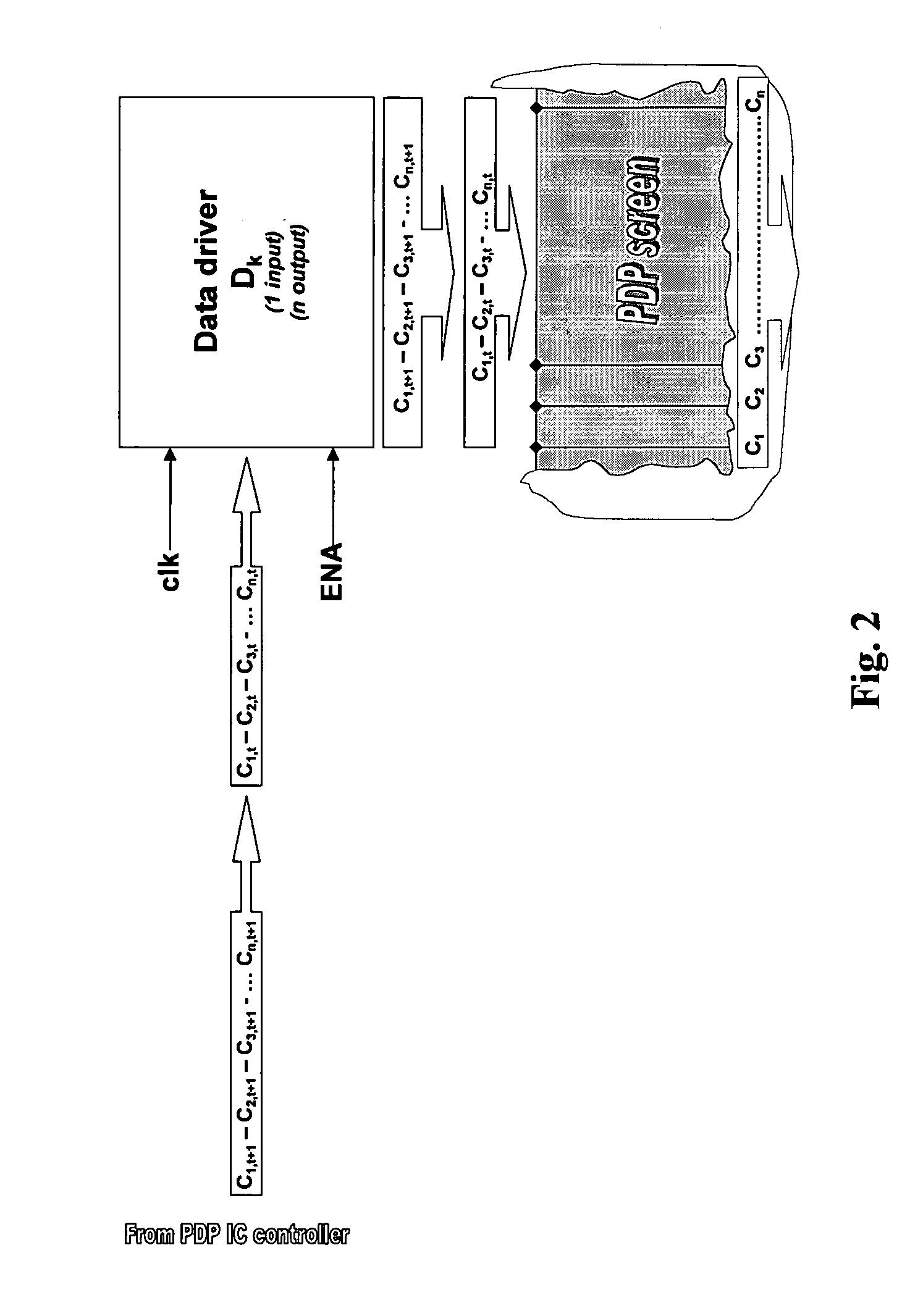
[0045] Each information Cx,t used for evaluating the heating contribution contains two types of information: [0046] Its value—0 or 1 and [0047] its horizontal transition to previous Cx−1,t having three possible stages: .

[0048] The emulator block 5 illustrated in FIG. 5 is a complex counter that will evaluate for each driver: [0049] The activity of the input by counting the number of differences between two consecutive, i.e. horizontally neighbouring inputs Cx,t+1, and Cx+1,t+1. Each time that a transition is detected (1→0 or 0→1), the input counter Cnt_INk is increased by a value HEAT_IN representing the impact of heating due to such a transition on driver Dk. [0050] The activity of the output by storing in a memory MEM_B...


PUM


Abstract

Overheating while enabling a full flexibility in the display usage should be avoided. This object is solved by a method for avoiding the overheating of a driver circuit in a plasma display panel wherein the driver circuit receives serially display data in form of a sequence of sub-field data bits and forwards parallelly the display data in the form of data blocks each consisting of a predefined number of sub-field data bits, the method comprising the steps of counting sub-field data bits the value of which differs from that of a neighbouring or preceding sub-field data bit and providing a respective counting signal indicative of heat contributions of sub-field data bits and, if said counting signal is above a pregiven threshold, taking countermeasures for reducing said temperature.

Description

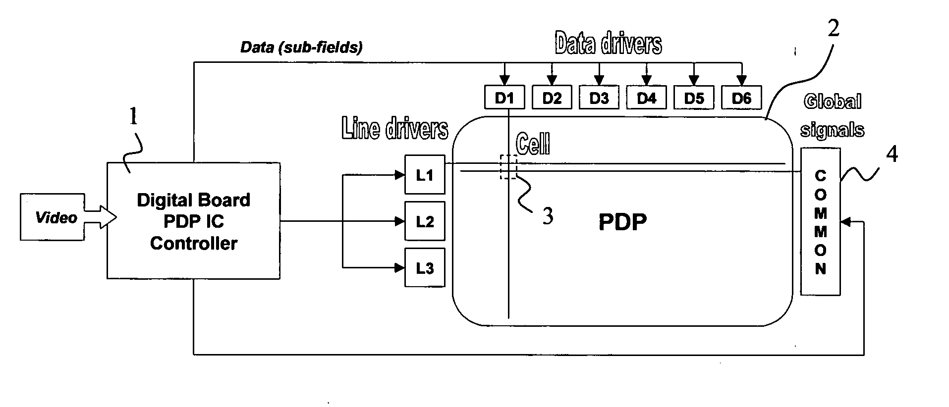
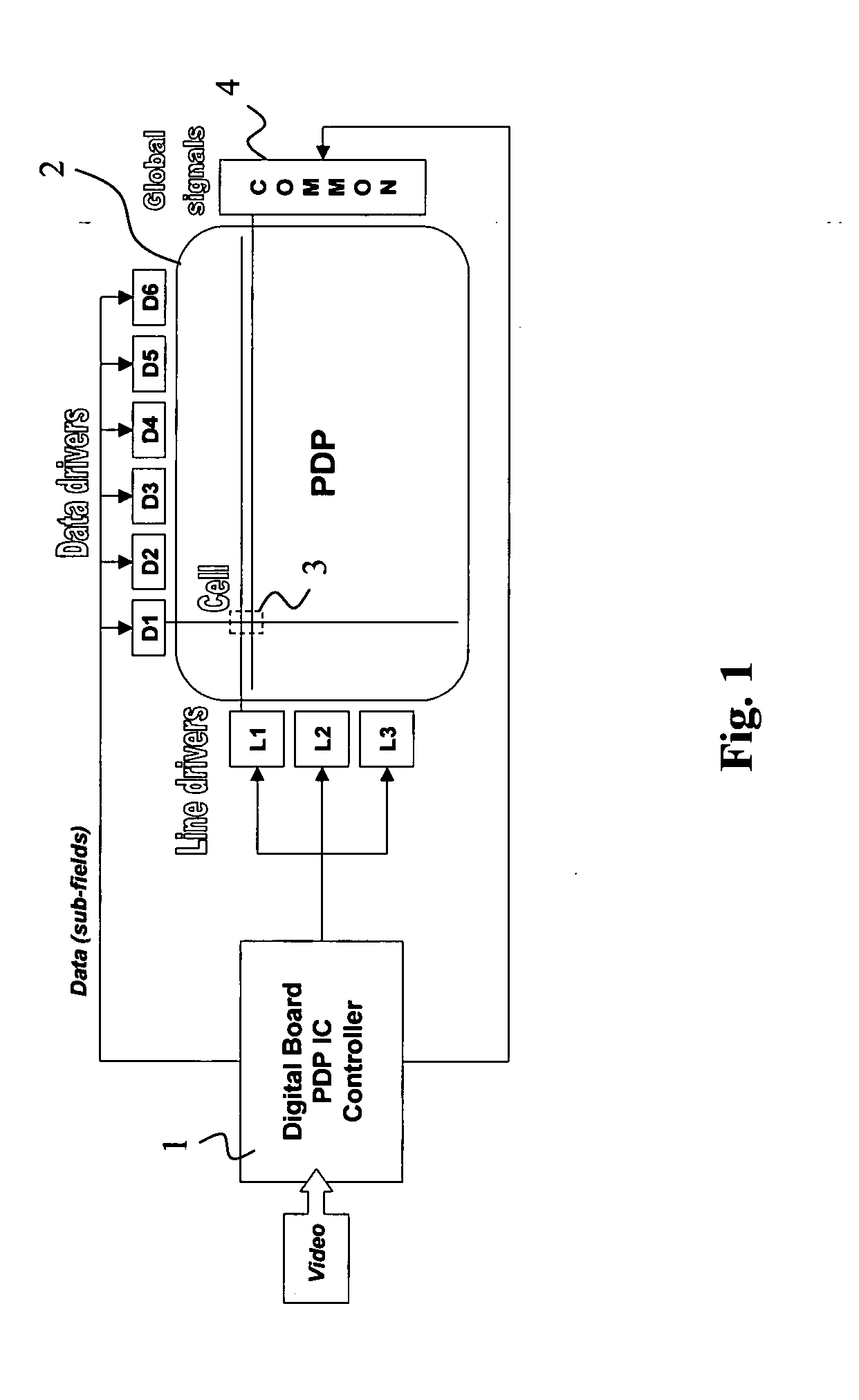
FIELD OF THE INVENTION [0001] The invention relates to a method for driving a plasma display panel including the steps of serially receiving display data in form of a sequence of subfield data bits and parallelly forwarding the display data in the form of data blocks each consisting of a pre-defined number of sub-field data bits. Furthermore, the present invention relates to a corresponding apparatus for driving a plasma display panel. BACKGROUND OF THE INVENTION [0002]FIG. 1 shows the principal structure of the electronics of a known plasma display panel (PDP). [0003] A video signal is sent to a Digital Board 1 that includes the heart of the PDP processing: the PDP IC controller. This IC takes care of all PDP relevant signal processing and converts video data to sub-field information as usual. Furthermore, the IC is responsible for sending all power signals to the hardware including: [0004] data drivers D1 to D6 of a PDP 2 for sending on the vertical electrodes the bits (1 or 0) fo...

Claims


Application Information

Patent Timeline
IPC IPC(8): G09G3/28
CPCG09G3/2037G09G2330/045G09G2320/0271G09G3/28
Inventor WEITBRUCH, SEBASTIENTHEBAULT, CEDRICCORREA, CARLOS
Owner THOMSON LICENSING SA
Learn More