
Vision Measurement and Training System and Method of Operation Thereof

Active Publication Date: 2007-08-30
GENENTECH INC
View PDF37 Cites 255 Cited by
  • Summary
  • Abstract
  • Description
  • Claims
  • Application Information

AI Technical Summary

Benefits of technology

[0019]Fortunately, computer graphics and gaming technology has now advanced to the level that low cost, highly effective devices for vision diagnosis, tracking and training can be envisioned. Binocular viewers allow each eye to be measured or trained independently or together, advances in variab

Problems solved by technology

These screening and measurement procedures are normally performed in a specialist's office and often include complex and expensive vision measurement instruments and time consuming interaction between the care provider and the patient.
While the need for high quality vision measurement and screening systems is very well established and accepted, vision training has been a topic of controversy.
In the past, some of these therapies have made claims of “miracle cures” for eye disease and, in some cases, no scientific basis or proof of effectiveness has been available.
This has lead some to believe that vision training is not effective.
Regrettably, such devices are somewhat cumbersome, have limited or no ability to measure vision function and are rather boring to operate making it difficult to fully engage a patient in the training regimen.
This last issue is especially problematic for use with children.
Regrettably, Mateik's device cannot measure a patient's vision performance nor adapt automatically to create an effective training system.
As the lenses are fixed for a given training session, only limited ranges and accommodations are possible.

Method used


Image

  • Vision Measurement and Training System and Method of Operation Thereof
  • Vision Measurement and Training System and Method of Operation Thereof
  • Vision Measurement and Training System and Method of Operation Thereof

Examples


Embodiment Construction

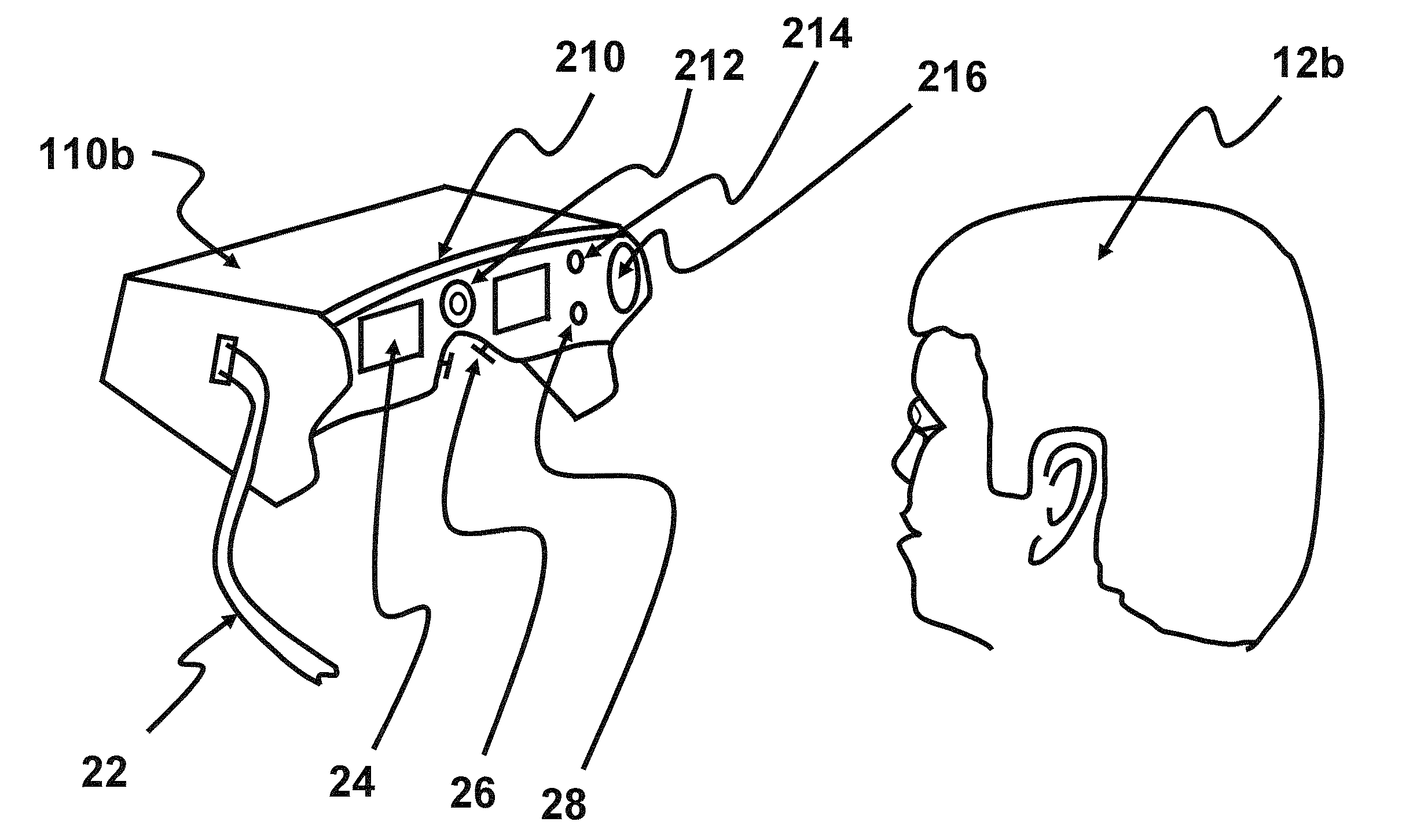
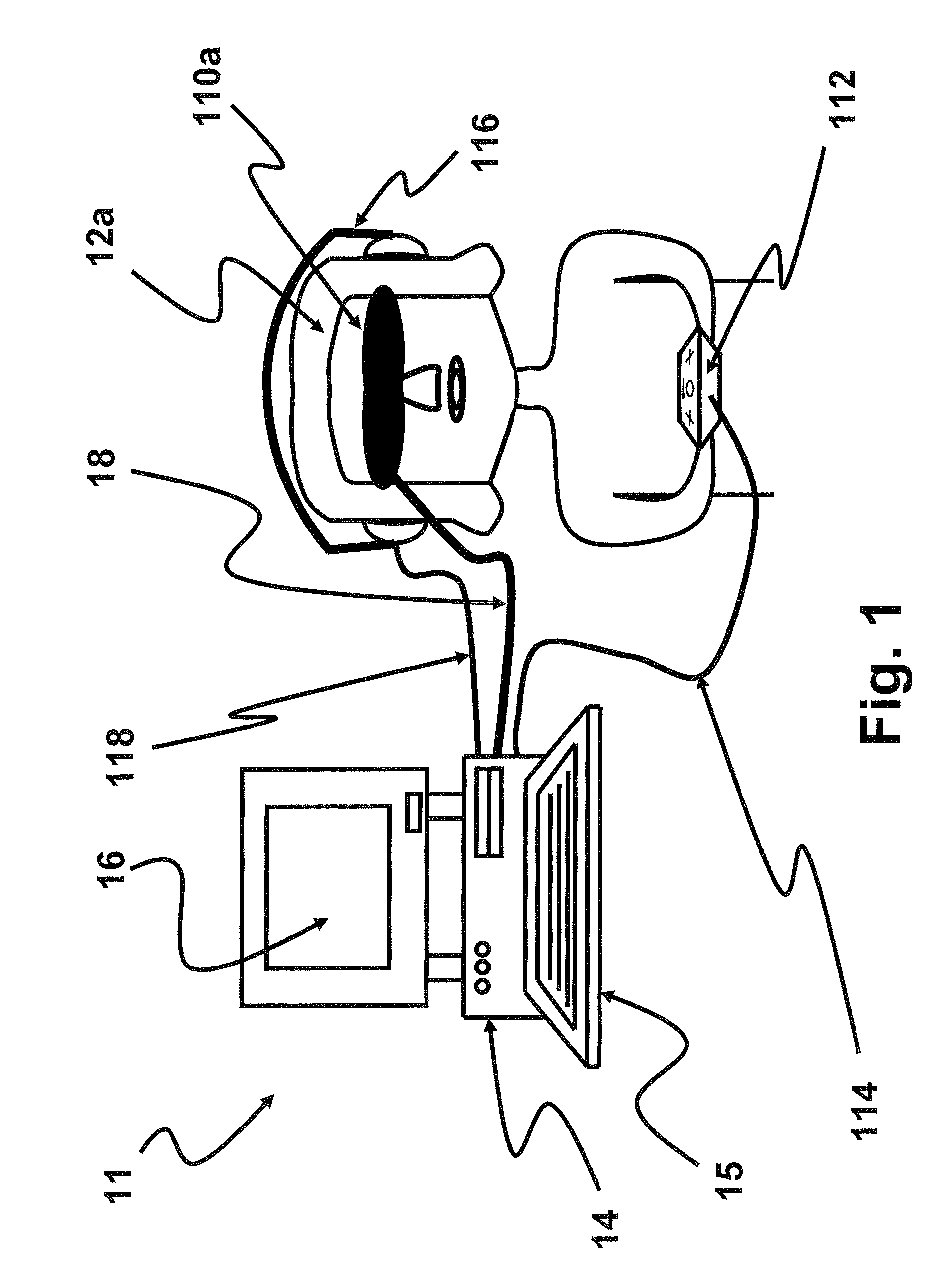
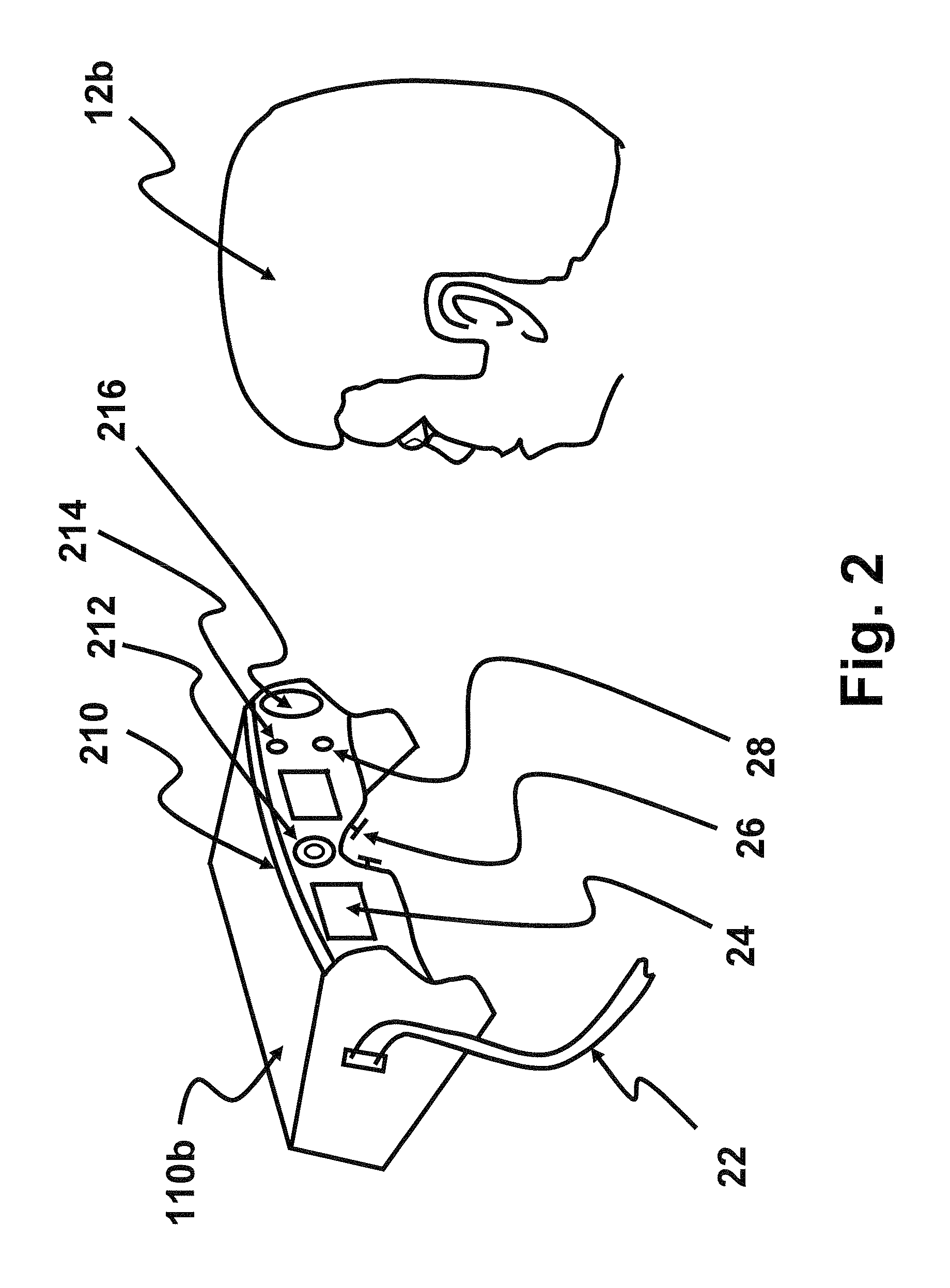
[0047]One aspect of the invention is directed to a vision measurement and training system that includes a computer, a binocular viewer, and a human input device. The computer generates video graphics with which the user interacts. By monitoring the user's responses, the system can diagnose vision conditions, track vision performance and provide vision training. Another aspect of the invention is directed to a variable focal depth function in the binocular viewer that can be controlled so that focusing disorders can be diagnosed, retinal disorders can be more accurately diagnosed and tracked, and vision training can include control of focal depth. Yet another aspect of the invention is directed to special images that provide benefit in vision measurement and / or training. Still another aspect of the invention is directed to techniques to ensure alignment of a user's face and eyes to the binocular viewer are consistent and that any misalignment is either signaled to the user or account...


PUM


Abstract

A binocular viewer, a method of measuring and training vision that uses a binocular viewer and a vision measurement and training system that employs a computer to control the binocular viewer. In one embodiment, the binocular viewer has left and right display elements and comprises: (1) a variable focal depth optical subsystem located in an optical path between the display elements and a user when the user uses the binocular viewer and (2) a control input coupled to the left and right display elements and the variable focal depth optical subsystem and configured to receive control signals operable to place images on the left and right display elements and vary a focal depth of the variable focal depth optical subsystem. In another embodiment, the binocular viewer lacks the variable focal depth optical subsystem, but the images include at least one feature unique to one of the left and right display elements.

Description

CROSS-REFERENCE TO RELATED APPLICATIONS[0001]This application claims priority based on the following U.S. provisional patent applications, which are commonly owned with this application and incorporated herein by reference:[0002]Ser. No. 60 / 776,614, filed by Krenik on Feb. 27, 2006;[0003]Ser. No. 60 / 791,809, filed by Krenik on Apr. 13, 2006;[0004]Ser. No. 60 / 796,580, filed by Krenik on May 1, 2006; and[0005]Ser. No. 60 / 802,362, filed by Krenik on May 22, 2006.TECHNICAL FIELD OF THE INVENTION[0006]The invention is directed, in general, to optical diagnosis and treatment devices and, more particularly, to a vision measurement and training system and a method of operating the same.BACKGROUND OF THE INVENTION[0007]There is no question that the ability to see clearly is a most treasured and valued human ability. Regrettably, many vision disorders commonly exist. Focusing disorders such as near-sightedness (myopia), far-sightedness (hyperopia) and astigmatism are very common and are norma...

Claims


Application Information

Patent Timeline
IPC IPC(8): H04N13/02
CPCA61B3/032A61H5/005A61B3/036A61B3/024A61H23/02A61H2201/0207A61H2201/10A61H2201/1604A61H2201/165A61H2201/501A61H2201/5043A61H2201/5048A61H2201/5058A61H2201/5092A61H2201/5097A61B3/0033A61B3/08
Inventor KRENIK, WILLIAM R.
Owner GENENTECH INC
Learn More