Locking device and connector provided with the same

a technology of electronic devices and locking devices, which is applied in the direction of coupling device connections, incorrect coupling prevention, engagement/disengagement of coupling parts, etc., can solve the problems of strong locking force of locking devices and difficulty in breaking, and achieve the effect of strong locking force and difficulty in breaking

Active Publication Date: 2007-08-30
JAPAN AVIATION ELECTRONICS IND LTD
View PDF4 Cites 22 Cited by
  • Summary
  • Abstract
  • Description
  • Claims
  • Application Information

AI Technical Summary

Benefits of technology

[0028]With the arrangement of the connector device according to the second aspect of the present invention, the connector device is locked with a strong locking force and the locking device thereof is difficult to be broken.

Problems solved by technology

Therefore, the locking device has a strong locking force and is difficult to be broken.

Method used


Image

  • Locking device and connector provided with the same
  • Locking device and connector provided with the same
  • Locking device and connector provided with the same

Examples


Embodiment Construction

[0042]Hereinafter, a preferred embodiment of the present invention will be described in detail with reference to the drawings.

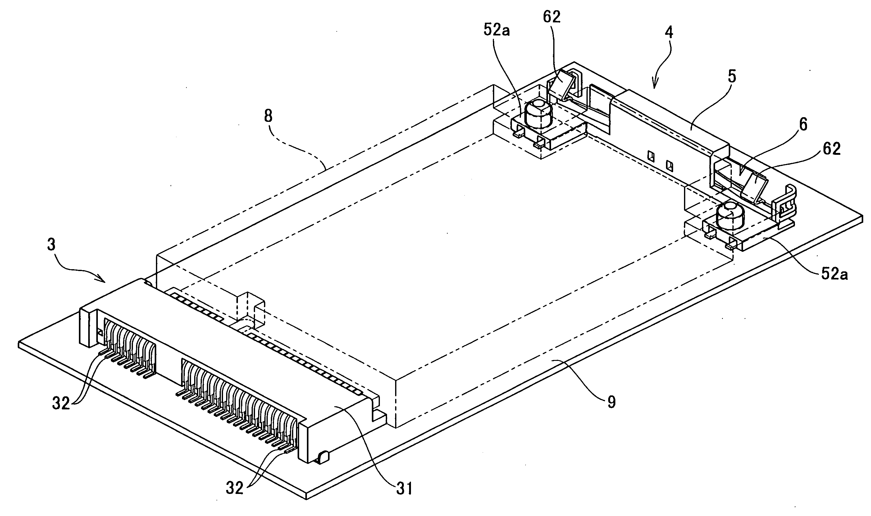
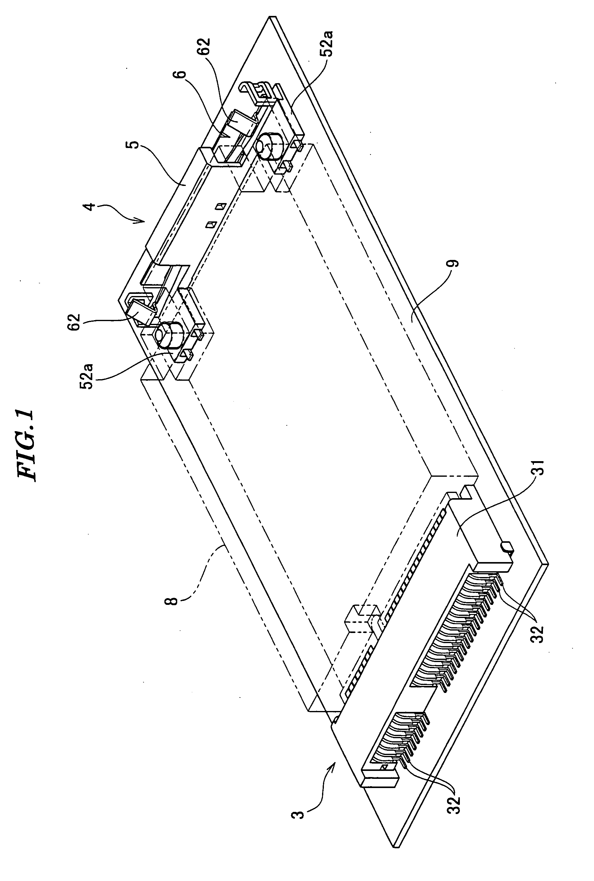
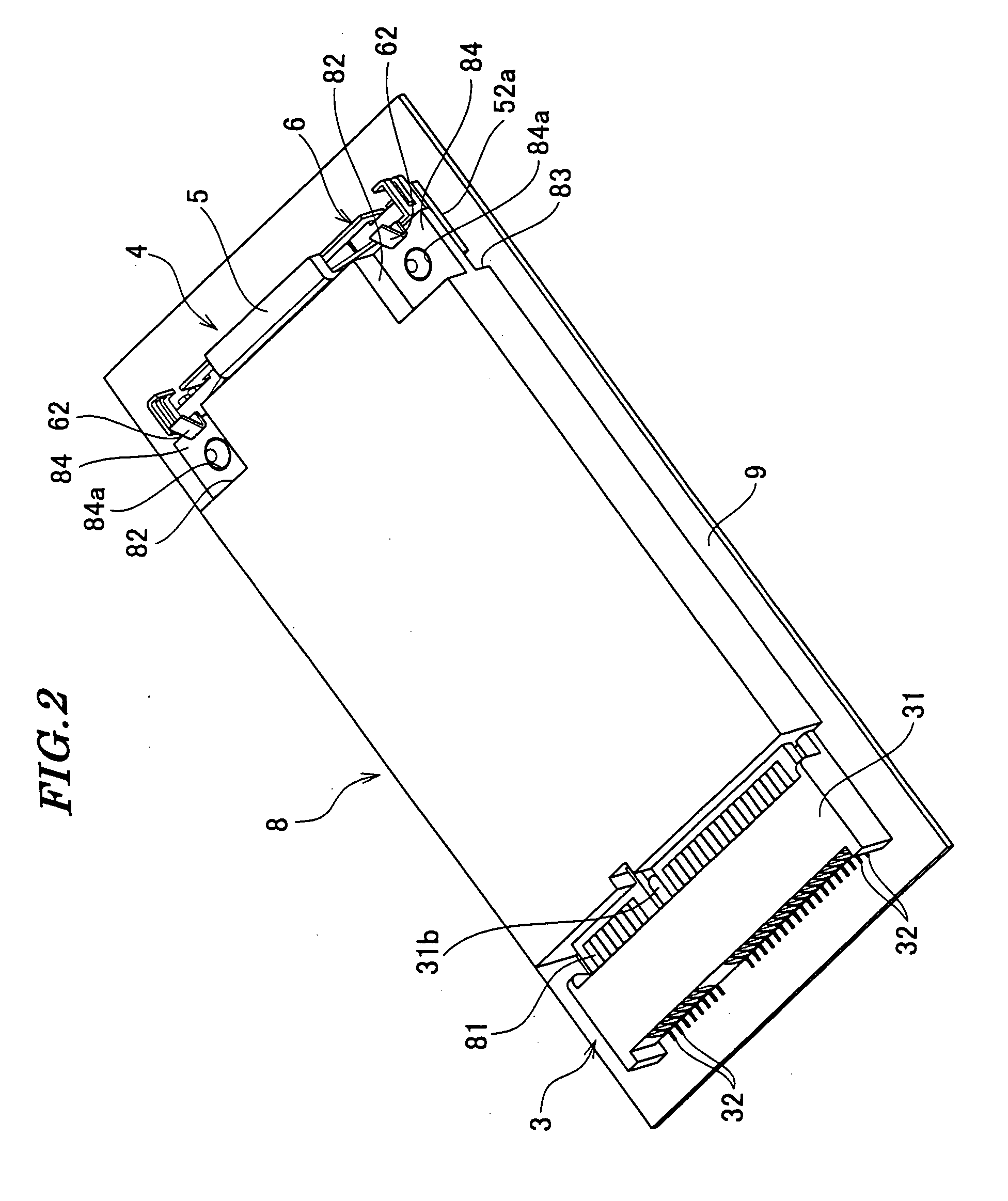
[0043]FIG. 1 is a perspective view of a connector device including a locking device according to an embodiment of the present invention. FIG. 2 is a perspective view of the connector device in a state in which a function expansion card is connected thereto.

[0044]Referring to FIG. 1, the connector device is for a function expansion card (card-type electronic device) 8, and is mounted on a printed wiring board (circuit board) 9. The connector is comprised of a connector body (connector) 3 and the locking device 4. The function expansion card 8 has a front end (one end) provided with a connecting portion 81. A rear end (the other end) of the function expansion card 8 has recesses 82 and 83 formed in respective upper and lower surfaces of each of opposite corners thereof. The recesses 82 and 83 are in a front-back relationship with respective thin portions 84 the...


PUM


Abstract

A locking device which has a strong locking force and is difficult to be broken. Leaf springs bending in a direction toward or away from the rear end of a function expansion card are provided in a housing, and locking sections for locking the function expansion card are connected to the leaf springs. Guide sections are provided in the housing, for guiding the outer ends of the leaf springs in the direction of bending of the leaf springs.

Description

BACKGROUND OF THE INVENTION[0001]1. Field of the Invention[0002]This invention relates to a locking device for a card-type electronic device, and a connector device for a card-type electronic device, provided with the locking device.[0003]2. Prior Art[0004]Conventionally, there has been proposed an edge connector provided with a housing, lower contacts, upper contacts, and locking mechanisms (see Japanese Laid-Open Patent Publication (Kokai) No. H08-250238 (Paragraph numbers [0011] to [0017], and [0020], and FIG. 1).[0005]The housing is comprised of a body extending in the left-right direction, and arm sections extending backward from the left and right ends of the body. The body is formed with a circuit board-receiving groove. In a lower surface of an upper wall of the circuit board-receiving groove, upper contact-receiving grooves extending in the front-rear direction are formed along the left-right direction at equal space intervals.[0006]The circuit board-receiving groove has a ...

Claims


Application Information

Patent Timeline
Patent Type & Authority Applications(United States)
IPC IPC(8): H01R13/62
CPCH01R13/6275H01R12/71H01R13/64
Inventor YAHIRO, YASUFUMITODA, KENTAROMORITAKE, TOSHIYUKI
Owner JAPAN AVIATION ELECTRONICS IND LTD
Why Eureka
Try Eureka