Power push pole

Inactive Publication Date: 2007-08-30
HARDWICK CHARLES W
View PDF13 Cites 5 Cited by
  • Summary
  • Abstract
  • Description
  • Claims
  • Application Information

AI Technical Summary

Benefits of technology

[0008] The primary object of the present invention is to provide a power

Problems solved by technology

Although this procedure seems simple to perform, actually it is quite the contrary.
Walking the pole is not only tiresome but dangerous as well as a person can easily lose his or her balance while performing the maneuver.
In addition, because a user will

Method used


Image

  • Power push pole
  • Power push pole
  • Power push pole

Examples


first embodiment

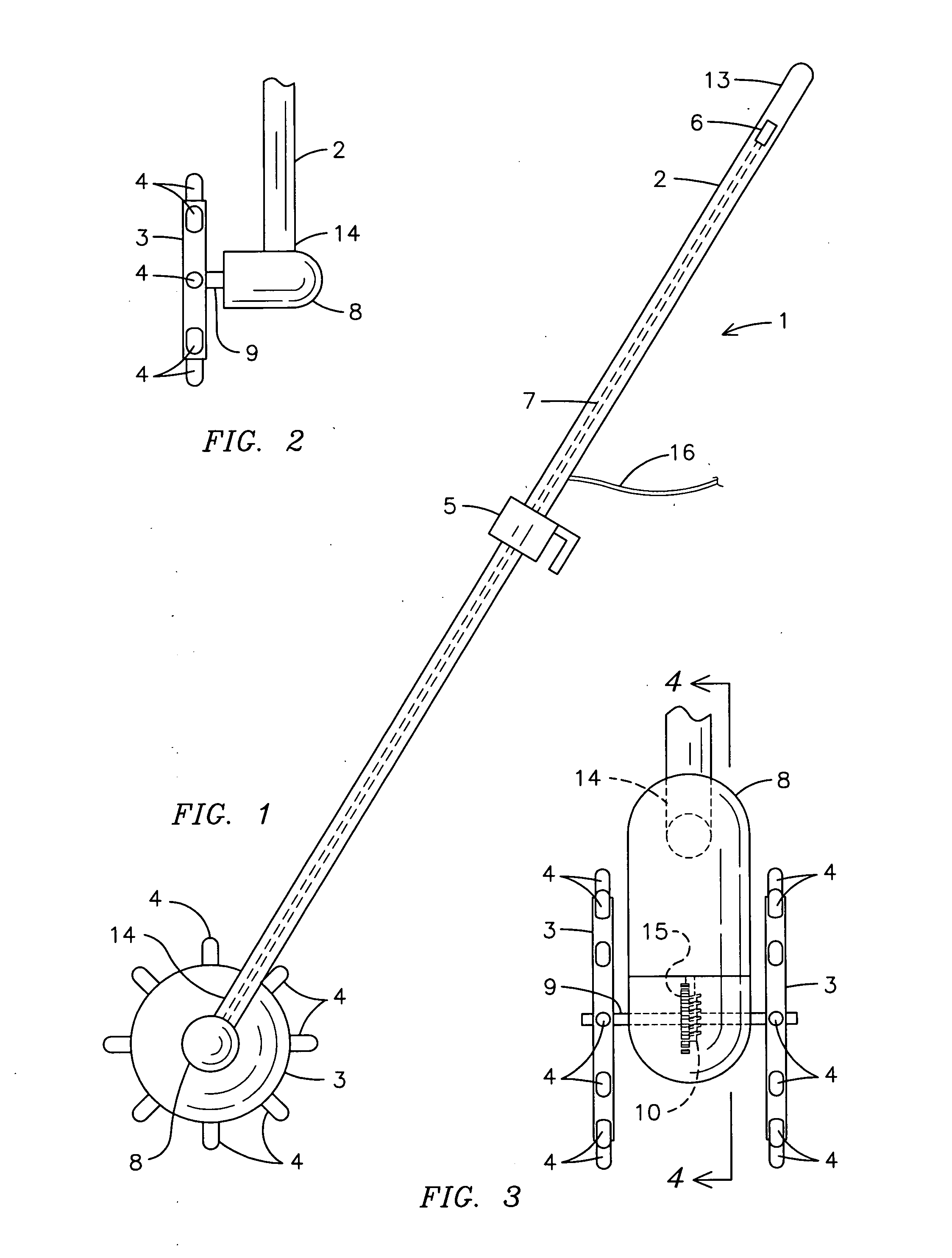
[0040] With reference to FIG. 1, a plan view of the power push pole of the present invention is shown. The power push pole 1 comprises an elongated handle 2 having a proximal end 13 and a distal end 14, a motor 8 secured to the distal end 14 of the handle and at least one drive wheel 3 is secured to the motor 8. The drive wheel 3 includes a plurality of extending members 4 which radiate from the drive wheel 3, such as spikes. A wire 7 connects the motor 8 to a control 6 located on the handle 2. The control 2 permits a user to turn the power push pole 1 on and off. In addition, the control 2 may provide for varying predetermined speeds, such as slow, medium and fast, and varying predetermined directions, such as forward and reverse, of the drive wheel 3. An optional fastening means, such as a bracket 5, may be attached to the handle 2 so as to permit a user to secure the power push pole 1 to the side of a vessel or stern or polling platform.

[0041]FIG. 2 shows a front view of a drive ...

second embodiment

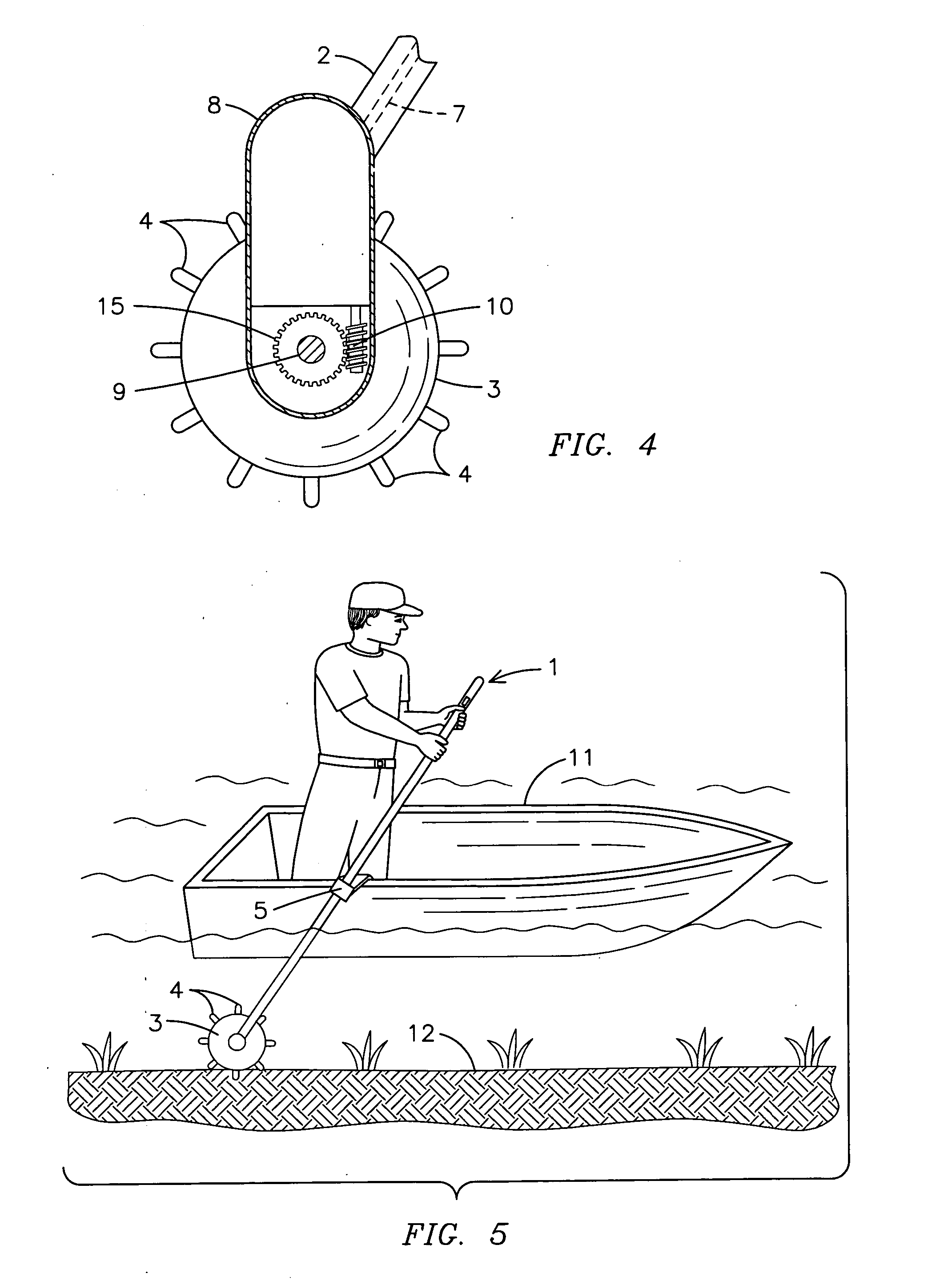
[0043]FIG. 4 shows a cross-sectional view of the motor 8 section of the present invention along line 4-4 of FIG. 3. The horizontal shaft 9 runs through the center of the cog wheel 15. The cog wheel 15, in turn, is located adjacent to and in operation with the worm gear 10. When a user turns on the power push pole 1 via the control 6, an electrical signal powered by a power source, preferably a 12 Volt / 24 Volt battery, is sent to the control 6 via wiring to the power source 16. The wire 7 from the control 6 then transmits power to the motor 8 to power the drive wheels 3. The motor 8 is sealed and covered, preferably with oil to protect the worm gear 10.

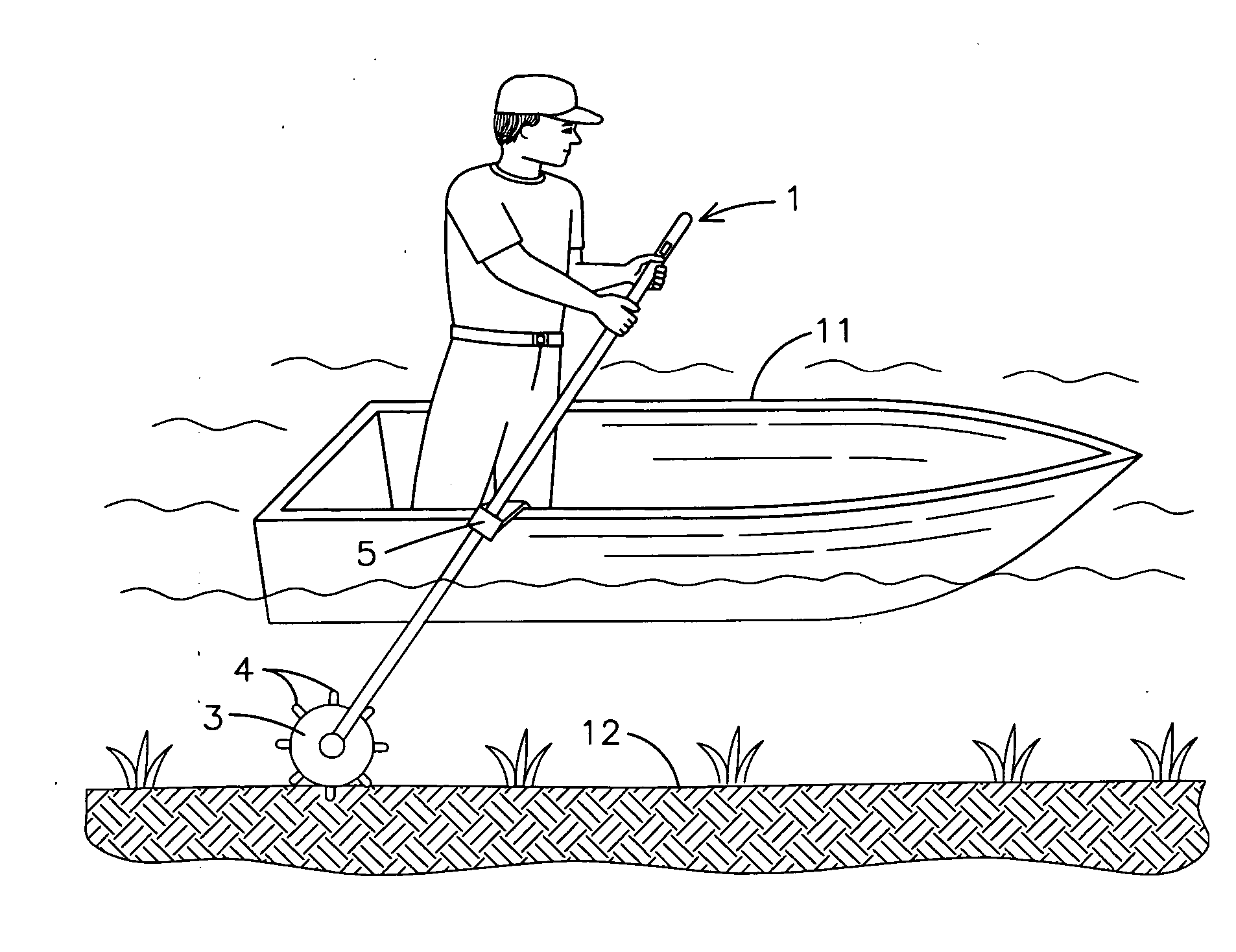
[0044] Finally, FIG. 5 shows a perspective view of the power push pole of the present invention in use. An optional bracket 5 may be secured to the transom or poling platform of a boat 11 so as to permit an individual to more easily maneuver the power push pole 1. Interchangeable extending members 4, such as spikes, and / or drive wheel ...


PUM


Abstract

A power push pole (1) having an elongated pole with a proximal end (13) and a distal end (14) wherein at least one drive wheel (3) with extending members (4) is located at the distal end (14) of the pole (1). An electric motor (8) is preferably located adjacent to the wheel (3) and is operable via at least one control (6) located on the proximal end (13) of the pole (1). Alternate embodiments of the invention include the use of dual wheels (3) for added stability, interchangeable extending members (4) and drive wheels (3) to accommodate varying ground textures, speed controls and forward/reverse controls. In addition, the power push pole (1) may be secured to a boat (11) via a fastener, such as a bracket (5).

Description

BACKGROUND OF THE INVENTION [0001] This invention relates to push poles, more particularly, a power push pole for use by boaters in shallow water fishing. [0002] The use of push poles by fishermen and women is not a new concept. Crude push poles consisting of long tree branches were used by early civilizations to propel a boat through shallow streams and rivers. [0003] Over time, however, the push pole developed in both style and sophistication. The need for longer push poles emerged wherein current push poles now have a length of 18-24 feet. The length of the push pole may be adjustable as well, as seen in many push poles that may be assembled by a user. In addition, the distal end of the poles may include points, hooks and other designs so as to permit a user to dig into the ground of the waterway. [0004] As the lengths of the push poles increased, the need for a lighter push pole became evident. Once made of wood or heavy metal, conventional push poles are now made of lightweight...

Claims


Application Information

Patent Timeline
IPC IPC(8): B63H16/00B63H19/00
CPCB63H19/08
Inventor HARDWICK, CHARLES W.
Owner HARDWICK CHARLES W
Why Eureka
Try Eureka