Storage control device, and data migration method using storage control device

a storage control device and data migration technology, applied in the field of storage control devices, can solve the problems of increasing the load on the microprocessor, limiting the usable capacity of the storage device, and high cost of the high-speed storage device, and achieves the effect of facilitating data migration, avoiding excessive load on the file controller, and facilitating data migration

Inactive Publication Date: 2007-08-30
HITACHI LTD
View PDF5 Cites 35 Cited by
  • Summary
  • Abstract
  • Description
  • Claims
  • Application Information

AI Technical Summary

Benefits of technology

[0009] The present invention has been conceived in the light of the above described problems, and its object is to provide a storage control device, and a data migration method which uses such a storage control device, which, by managing the update state of the logical storage devices which make up a virtual volume, can specify the data which is to be the migration subject in a comparatively simple manner, thus being able to migrate data efficiently. Another object of the present invention is to provide a storage control device, and a data migration method which uses such a storage control device, which, by managing the update states of the logical storage devices which make up a virtual volume by management units in a cache memory, can specify a file which is to be the migration subject indirectly without imposing any excessive load on the file controller, and can shift the data of this file which has been specified. A yet further object of the present invention is to provide a storage control device, and a data migration method which uses such a storage control device, which can perform migration of data in a comparatively simple manner without using any special commands, by creating a non-updated bitmap within a block controller and creating a migration subject bitmap within a file controller, the file controller and the block controller sharing these bitmaps and using them for copying between memories. Still further objects of the present invention will become clear from the embodiments thereof which will be described hereinafter.

Problems solved by technology

This is because a high speed storage device is generally of high cost, and there is a limit to its usable capacity.
However, the greater the volume size becomes, the more time is required for performing complete searching and so on of the file tree, so that the load on the micro processor is increased.
And, for example, with a so called NAS (Network Attached Storage) file server, there is the problem that an excessive load is imposed on the migration processing, in order to be able to construct a file system on a virtual volume of such a great size.

Method used


Image

  • Storage control device, and data migration method using storage control device
  • Storage control device, and data migration method using storage control device
  • Storage control device, and data migration method using storage control device

Examples


embodiment 1

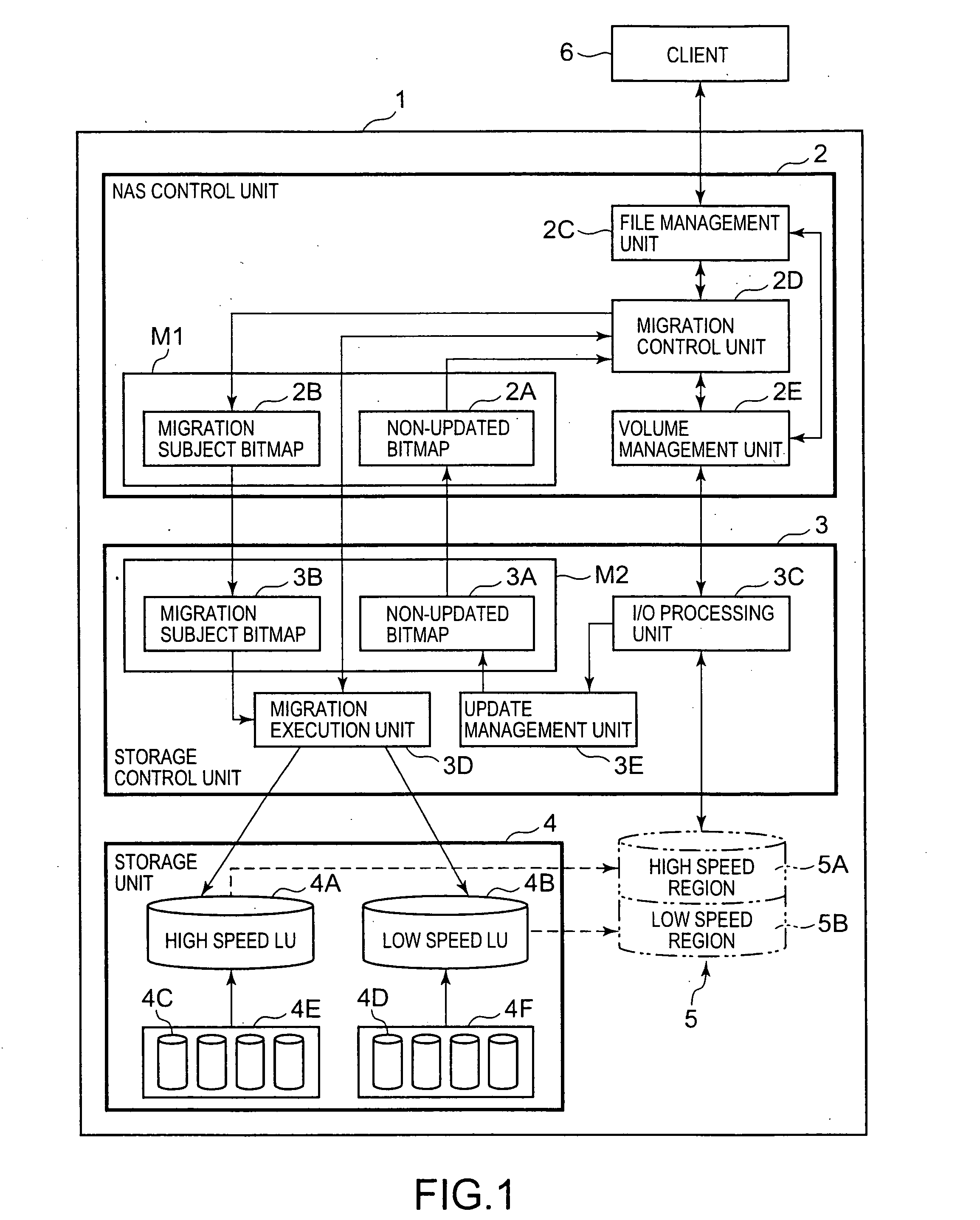
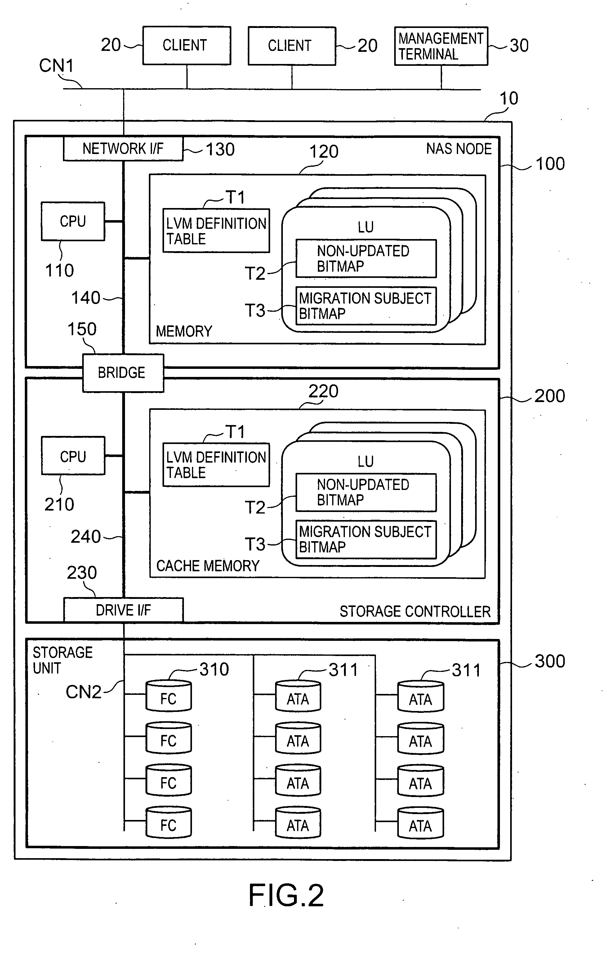
[0077]FIG. 2 is an explanatory structural figure showing the overall structure of the storage control device 10. First, to explain the correspondence relationship between this figure and FIG. 1: the storage control device 10 in FIG. 2 corresponds to the storage control device 1 in FIG. 1, the NAS node 100 in FIG. 2 corresponds to the NAS control unit 2 in FIG. 1, the storage controller 200 in FIG. 2 corresponds to the storage control unit 3 in FIG. 1, the storage unit 300 in FIG. 2 corresponds to the storage unit 4 in FIG. 1, and the client 20 in FIG. 2 corresponds to the client 6 in FIG. 1.

[0078] The storage control device 10 comprises, for example, the NAS node 100, the storage controller 200, and the storage unit 300. The storage control device 10 is connected to one or a plurality of client machines 20 and to a management terminal 30, via a communication network CN1 such as, for example, a LAN or the like. The client machines 20 are computer devices for performing input and out...

embodiment 2

[0158] A second embodiment of the present invention will now be explained based on FIG. 13 and FIG. 14. In this embodiment, the migration subject bitmap T3 is divided into a plurality of areas, and the data shifting is performed in units of segments for each of the areas. This embodiment and the other embodiments described hereinafter correspond to variations of the first embodiment.

[0159]FIG. 13 is an explanatory figure showing the situation in which a plurality of segment ranges are set for the migration subject bitmap T3. As shown in the upper portion of FIG. 13, segment ranges AS1 through AS3 are set in the migration subject bitmap T3, and the data migration is executed in units of segments for each of these segment ranges AS1 through AS3.

[0160] In the lower portion of FIG. 13, there is given a flow chart which shows the flow of processing for determining the size of the segment ranges. This processing shows the detail of the step S71 in FIG. 14. First, the migration tool 113 ...

embodiment 3

[0177] A third embodiment of the present invention will now be explained based on FIGS. 15 through 17. In this third embodiment, the case will be explained in which the structure of the virtual volume 340 is changed. As has been described in the explanation of the LVM definition table T1, it is possible to change the structure of the virtual volume 340.

[0178]FIG. 15 is an explanatory figure schematically showing the software structure of the NAS node 100 and the structure of the hierarchical storage. To the FC region of the virtual volume 340, there correspond a plurality of logical volumes 330 (LU0, LU2), each of which is founded on FC disks 310. And, to the ATA region of the virtual volume 340, there correspond a plurality of logical volumes 331 (LU1, LU3), each of which is founded on ATA disks 311.

[0179] And FIG. 16 is an explanatory figure, schematically showing a management state for the segments when the FC region and the ATA region are made up from a plurality of logical vo...


PUM


Abstract

The storage control device of the present invention performs data migration without any increase of the load on a NAS control unit. A volume based on a FC disk and a volume based on a ATA disk are joined together, so as to create one virtual volume. An update manager monitors updating of the high speed region, and creates update bitmaps. And the update manager calculates the OR of the update bitmaps, thus creating a non-updated bitmap for detecting segments which have not been updated for a predetermined time period. Based on this non-updated bitmap, a migration controller creates a migration subject bitmap by extracting segments which are to be subjects for migration. And a migration executant performs data migration for the migration subject segments one at a time or several together, based on this migration subject bitmap.

Description

CROSS-REFERENCE TO RELATED APPLICATION [0001] This application relates to and claims priority from Japanese Patent Application No. 2006-47799 filed on Feb. 24, 2006, the entire disclosure of which is incorporated herein by reference. BACKGROUND OF THE INVENTION [0002] 1. Field of the Invention [0003] The present invention relates to a storage control device, and to a method for migrating data using a storage control device. [0004] 2. Description of the Related Art [0005] Although the amount of data which must be managed in a business or the like increases day by day, generally, the frequency of use of data decreases after a fixed time period has elapsed from when it was created. Since the value of the data decreases along with the passage of time, data whose utilization value has become small ought to be transferred from a high speed storage device to a low speed storage device. This is because a high speed storage device is generally of high cost, and there is a limit to its usable...

Claims


Application Information

Patent Timeline
Patent Type & Authority Applications(United States)
IPC IPC(8): G06F13/00G06F12/00
CPCG06F3/0608G06F3/061G06F3/067G06F3/0664G06F3/0649
Inventor MUROTANI, AKIRAHIGAKI, SEIICHI
Owner HITACHI LTD
Why Eureka
Try Eureka