Feeder for punch

Inactive Publication Date: 2007-09-06
ELITE MACHINE & DESIGN
View PDF6 Cites 1 Cited by
  • Summary
  • Abstract
  • Description
  • Claims
  • Application Information

AI Technical Summary

Benefits of technology

[0007] An advantage of the feeder of the present invention is improved safety for an operator since the operator can stay away from the bending unit because of the automatic operation of the bending unit.
[0008] Another advantage of the feeder of the present invention is improved throughput due to the automatic operation of the bending unit.

Problems solved by technology

Otherwise, undesired situations would occur.

Method used


Image

  • Feeder for punch
  • Feeder for punch
  • Feeder for punch

Examples


Embodiment Construction

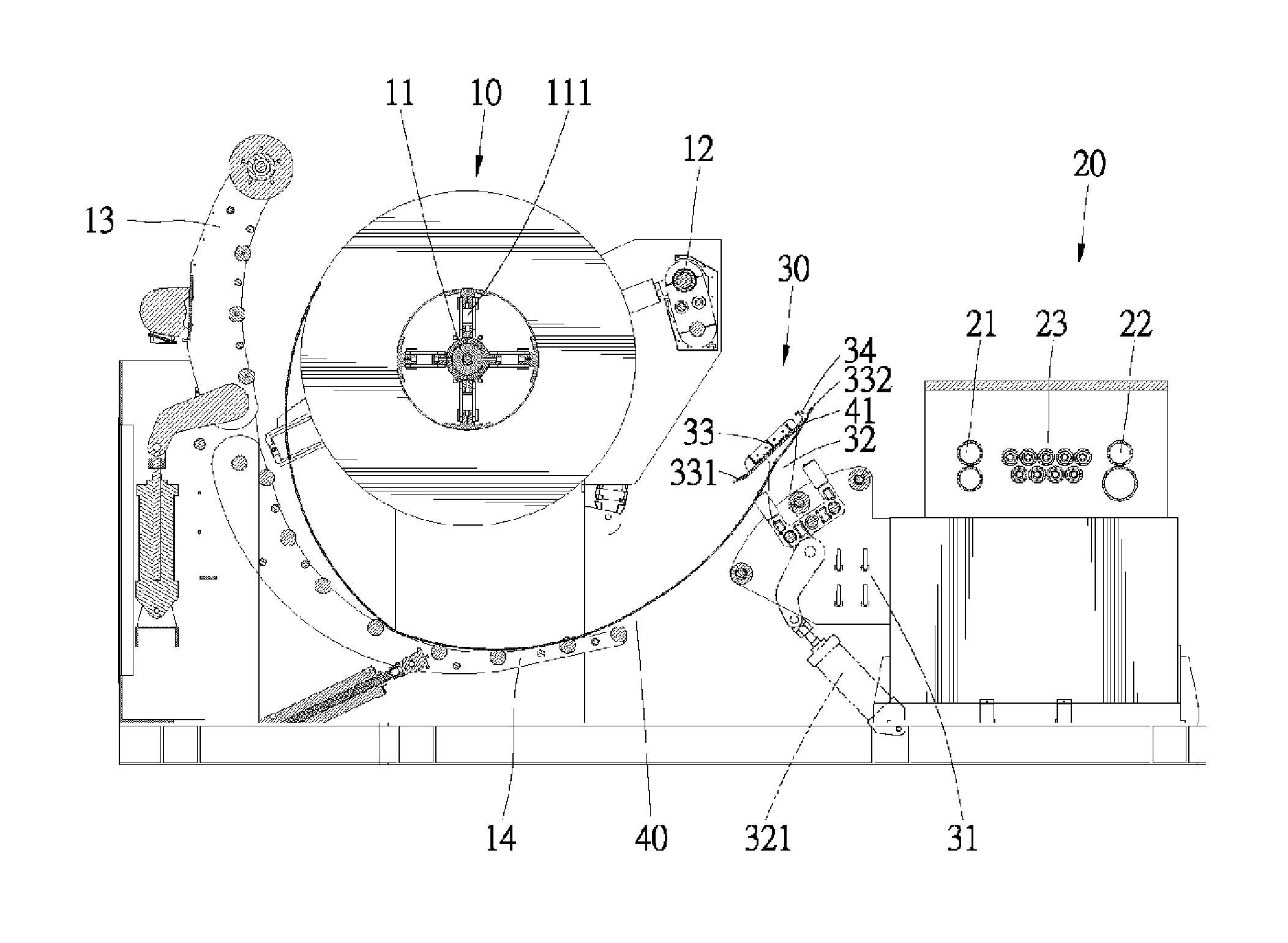
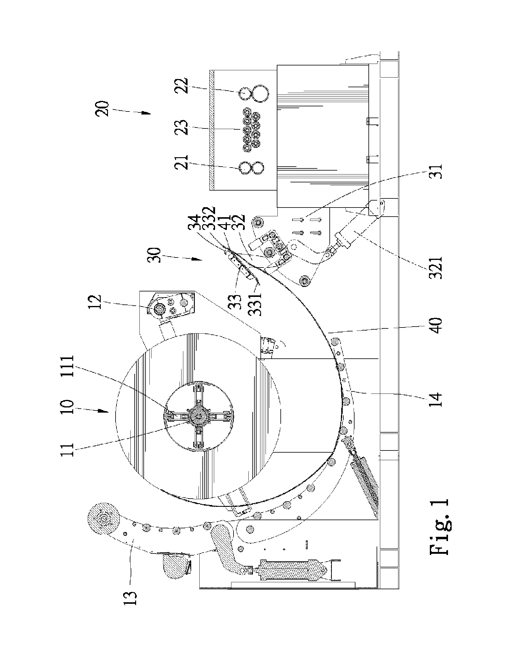
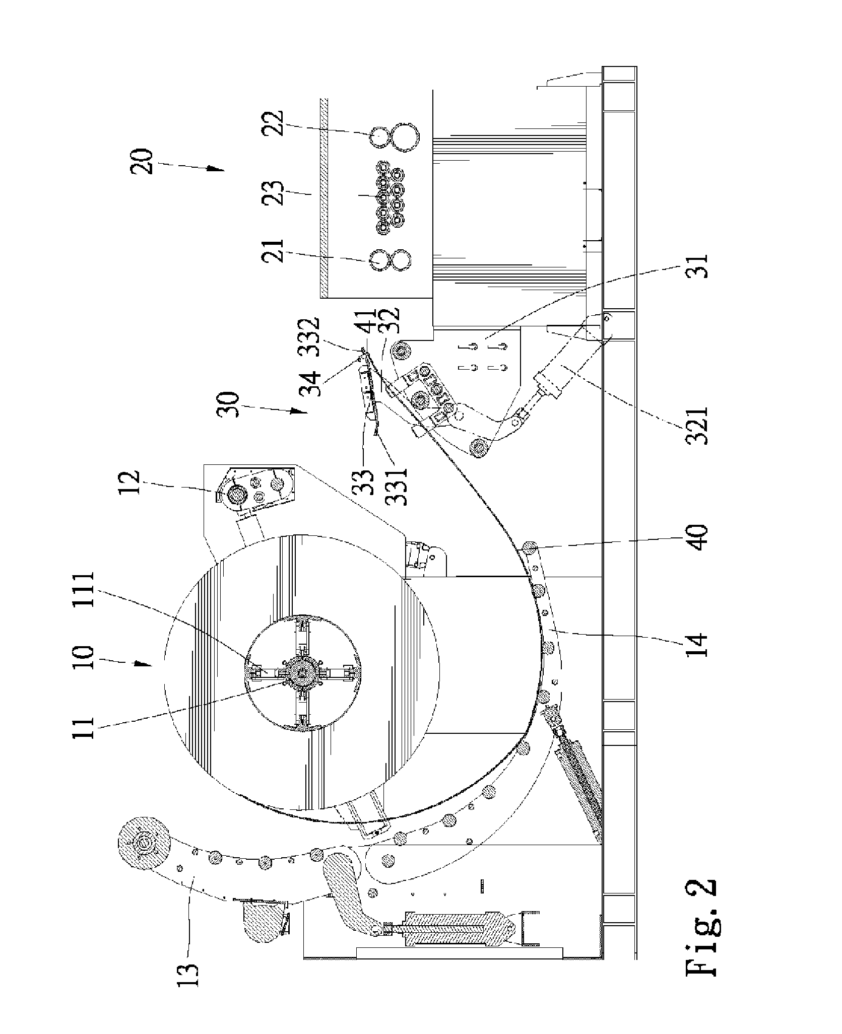
[0018] Referring to FIGS. 1 through 4, there is shown a feeder for a punch according to the preferred embodiment of the present invention. The feeder includes a feeding unit 10, a bending unit 30 and a transferring unit 20. A metal strip 40 is rolled. The roll of the metal strip 40 is installed on the feeding unit 10. The feeding unit 10 rotates the roll so as to feed the metal strip 40. On reaching the bending unit 30, a leading edge 41 of the metal strip 40 travels at a large curvature. The bending unit 30 pivots so as to bend the metal strip 40. When leaving the bending unit 30, the leading edge 41 of the metal strip 40 travels at a small opposite curvature. The bending unit 30 guides the metal strip 40 to the transferring unit 20. The transferring unit 20 transfers the metal strip 40 to another unit of the punch.

[0019] The feeding unit 10 includes a shaft 11 for rotation and a plurality of spoke-liked extenders 111 extensible from the shaft 11 to the roll of the metal strip 40....


PUM


Abstract

A feeder is provided for a punch. The feeder includes a feeding unit, a bending unit and a transferring unit. The feeding unit feeds a roll of a metal strip that includes a leading edge. The bending unit includes a plate for bending the metal strip, a sensor for generating at least one signal on detecting the arrival of the leading edge of the metal strip at the plate and a controller for actuating the plate on receiving the signal. The transferring unit transfers the metal strip to another unit of the punch.

Description

BACKGROUND OF INVENTION [0001] 1. Field of Invention [0002] The present invention relates to a punch and, more particularly, to a feeder for a punch. [0003] 2. Related Prior Art [0004] Referring to FIGS. 5 through 7, there is shown a conventional feeder for a punch. The feeder includes a feeding unit 1, a guiding unit 4, a bending unit 3 and a transferring unit 2. A metal strip or plate 5 is rolled. The roll is installed on the feeding unit 1. The feeding unit 1 rotates the roll so as to feed the metal strip 5. The guiding unit 4 guides the metal strip 5 to the bending unit 3. When reaching the bending unit 3, a leading edge of the metal strip 5 travels counterclockwise at a large curvature. The bending unit 3 pivots so as to bend the metal strip 5. When leaving the bending unit 3, the leading edge of the metal strip 5 travels clockwise at a small curvature. The bending unit 3 guides the metal strip 5 to the transferring unit 2. The transferring unit 2 transfers the metal strip 5 to...

Claims


Application Information

Patent Timeline
IPC IPC(8): B21D5/14
CPCB21D43/11
Inventor HO, CHI-MIN
Owner ELITE MACHINE & DESIGN
Why Eureka
Try Eureka