Method and apparatus for producing synthesis gas from waste materials

a technology of synthesis gas and waste materials, which is applied in the direction of oxygen compound purification/separation, combustible gas production, and separation processes, etc., can solve the problems of unwanted carbon dioxide, ash and slag production, and achieve the effect of avoiding carbon buildup in the apparatus and preventing unwanted reactions

Inactive Publication Date: 2007-09-06
BIOCONVERSION TECH LLC
View PDF11 Cites 26 Cited by
  • Summary
  • Abstract
  • Description
  • Claims
  • Application Information

AI Technical Summary

Benefits of technology

[0003] From the reformer reactor, the formed syn gas passes through a series of particulate separators to remove any formed ash. These separators are maintained at a temperature greater than 1500° F., by housing them in the same furnace as the reformer reactor. This prevents unwanted reactions which can occur when the syn gas cools, and avoids carbon buildup in the apparatus. The syn gas from the separator is rapidly quenched to a temperature well below 1000° F., preferably to a temperature of about 120° F. At this temperature, the syn gas is stable and will not form carbon deposits or allow unwanted reactions. At the same time the material is cooled, preferably in a quencher, any residual tar or oil is separated and either fed back to the devolatilization zone for reaction or collected for further use. In a further feature of the present invention, the heat from the devolatilization zone is directed to a preheater section where water and combustion air are circulated to recover residual heat.

Problems solved by technology

This produces unwanted carbon dioxide, ash and slag.

Method used


Image

  • Method and apparatus for producing synthesis gas from waste materials
  • Method and apparatus for producing synthesis gas from waste materials
  • Method and apparatus for producing synthesis gas from waste materials

Examples


Embodiment Construction

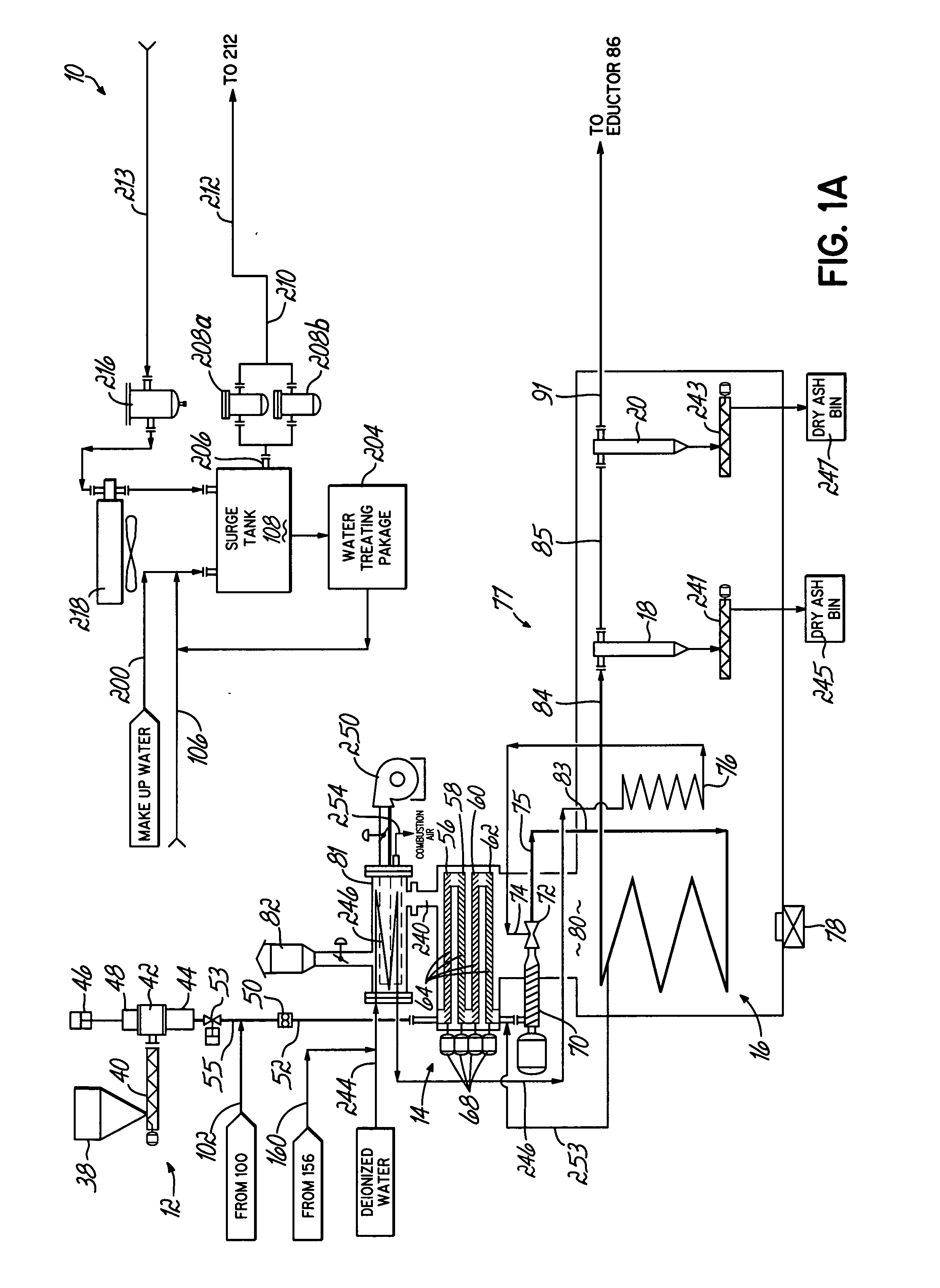
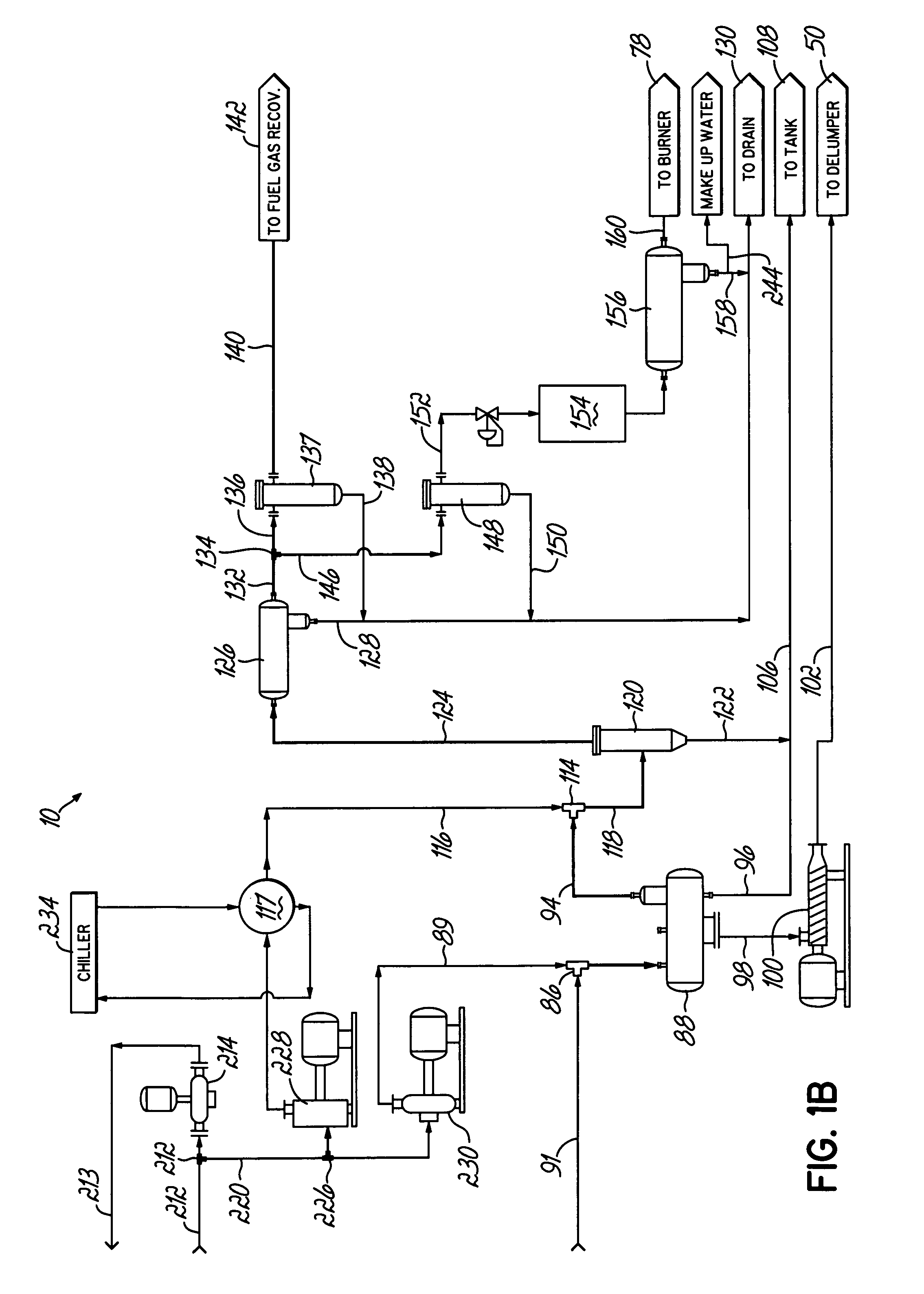
[0009] As shown diagrammatically in FIGS. 1A and 1B, syn gas facility 10 includes a feed section 12 which communicates with a devolatilization section 14, in turn connected to a reformer reactor 16. The reactor 16 is designed to produce syn gas which passes through particulate separators 18 and 20. The gas is cooled, filtered, and collected for use.

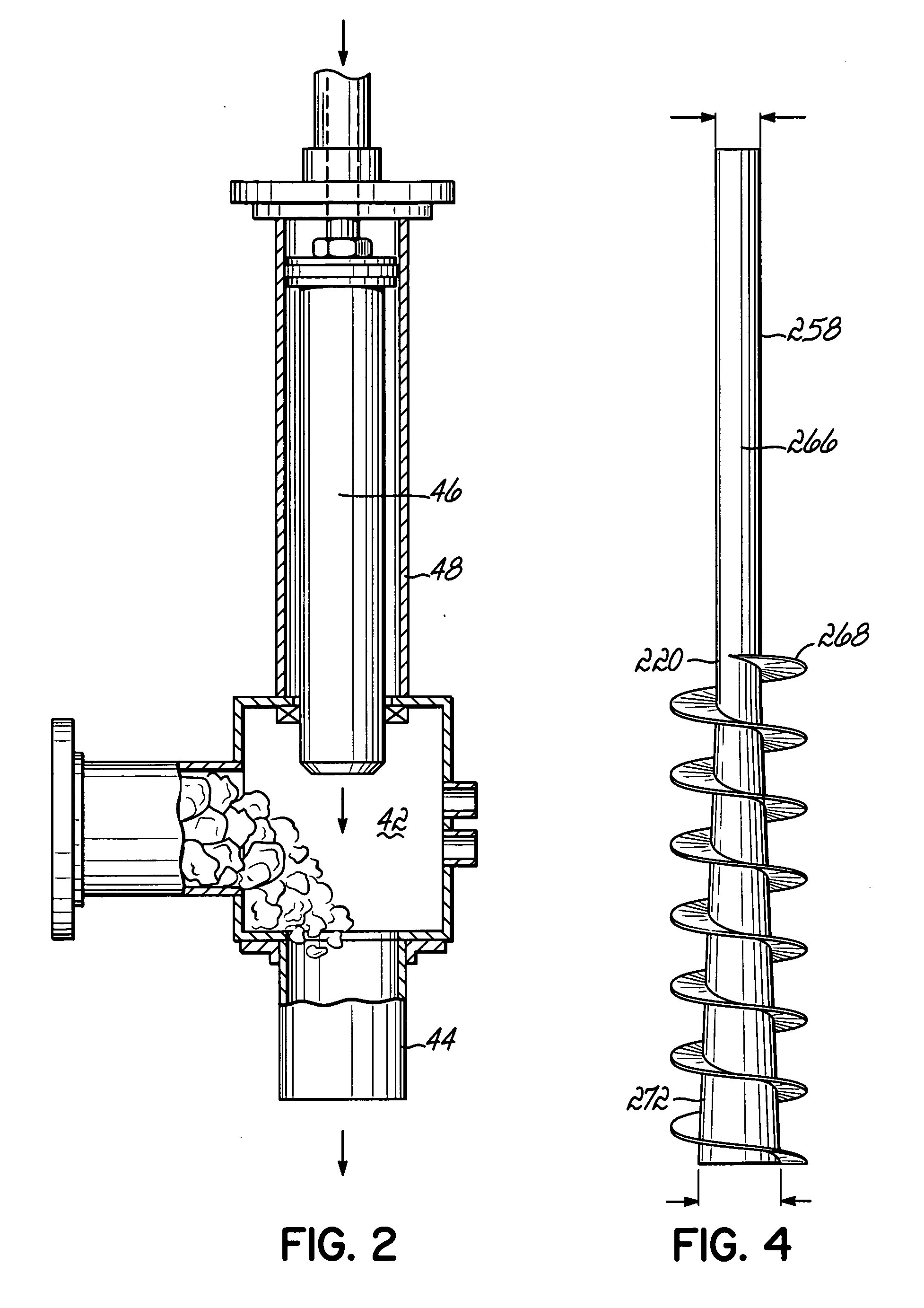
[0010] As shown more particularly in FIGS. 1 and 2, the feed section 12 includes a hopper 38 having an auger 40, which directs cabonaceous feed material to feed chamber 42. The feed chamber 42 is connected to a feed tube 44 which leads to the devolatilization section 14. Above the feed section is a cylindrical support 48 which supports a compacting cylinder 46 designed to force feed material from the feed chamber 42 into the feed tube 44. The feed tube 44 leads to a delumper 50, which communicates via passage 52 to the devolatilization section 14. A gate valve 53 prevents backflow through line 55 from delumper 50.

[0011] The devolatiliza...


PUM

PropertyMeasurementUnit
temperatureaaaaaaaaaa

Abstract

An apparatus designed to form syn gas from carbonaceous materials such as coal includes a devolatilization reactor in combination with a reformer reactor which subsequently forms syn gas. The reformer reactor, in turn, is in communication with a particulate separator. The devolatilization reactor is fed with material using a compression feeder which drives air from the feed material, compresses it in a feed zone forming a seal between the feed hopper and the devolatilization reactor. The reformer reactor, as well as the particulate separators, are maintained in a heated furnace so that the temperature of the formed syn gas does not decrease below the reaction temperature until particulate material has been separated.

Description

BACKGROUND OF THE INVENTION [0001] Carbonaceous material can be reacted with steam at elevated temperatures to form syn gas, which is a combination of carbon monoxide and hydrogen. As disclosed in U.S. Pat. No. 6,863,878, if the initial reaction reaches a temperature greater than about 450° F. before the available oxygen is reacted, combustion occurs. This produces unwanted carbon dioxide, ash and slag. To avoid this, as disclosed in U.S. Pat. No. 6,863,878, the temperature must be maintained at 450° F. until after the available oxygen is reacted. SUMMARY OF THE INVENTION [0002] The present invention is premised on the realization that syn gas can be produced more efficiently by modifying the process disclosed in U.S. Pat. No. 6,863,878, the disclosure of which is hereby incorporated by reference. In particular, the carbonaceous material in the devolatilization zone is maintained at a temperature less than 450° F. until all of the available oxygen is reacted. In the present inventio...

Claims


Application Information

Patent Timeline
Patent Type & Authority Applications(United States)
IPC IPC(8): C07C27/26B01D3/00C01B32/40
CPCC10J3/487C10J3/50C10J3/84C10J2200/15C10J2300/0973C10J2200/158C10J2300/0903C10J2300/093C10J2200/154
Inventor KLEPPER, ROBERT E.
Owner BIOCONVERSION TECH LLC
Why Eureka
Try Eureka