Ventilation system and method of using the ventilation system

a ventilation system and ventilation system technology, applied in ventilation systems, heating types, instruments, etc., can solve problems such as inefficiency of power vents, damage to roofs, water intrusion and mold growth,

Inactive Publication Date: 2007-09-06
BYCZYNSKI KENNETH C +1
View PDF37 Cites 33 Cited by
  • Summary
  • Abstract
  • Description
  • Claims
  • Application Information

AI Technical Summary

Problems solved by technology

The refreezing ice causes damage to the roof and eventually leads to water intrusion and mold growth.
However, a power vent requires power to drive the fan and a power vent may be inefficient if it is powered constantly.
In addition, if the attic is cooler and less humid than the air of the exterior of the building, the power vent will force the warmer and more humid air from the exterior of the building to the attic thereby undesirably increasing the temperature and humidity of the air in the attic.

Method used


Image

  • Ventilation system and method of using the ventilation system
  • Ventilation system and method of using the ventilation system
  • Ventilation system and method of using the ventilation system

Examples


first embodiment

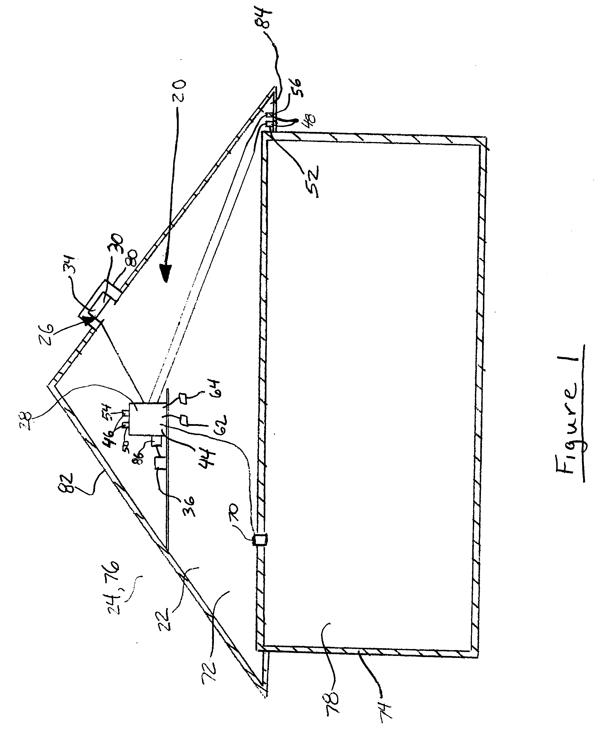
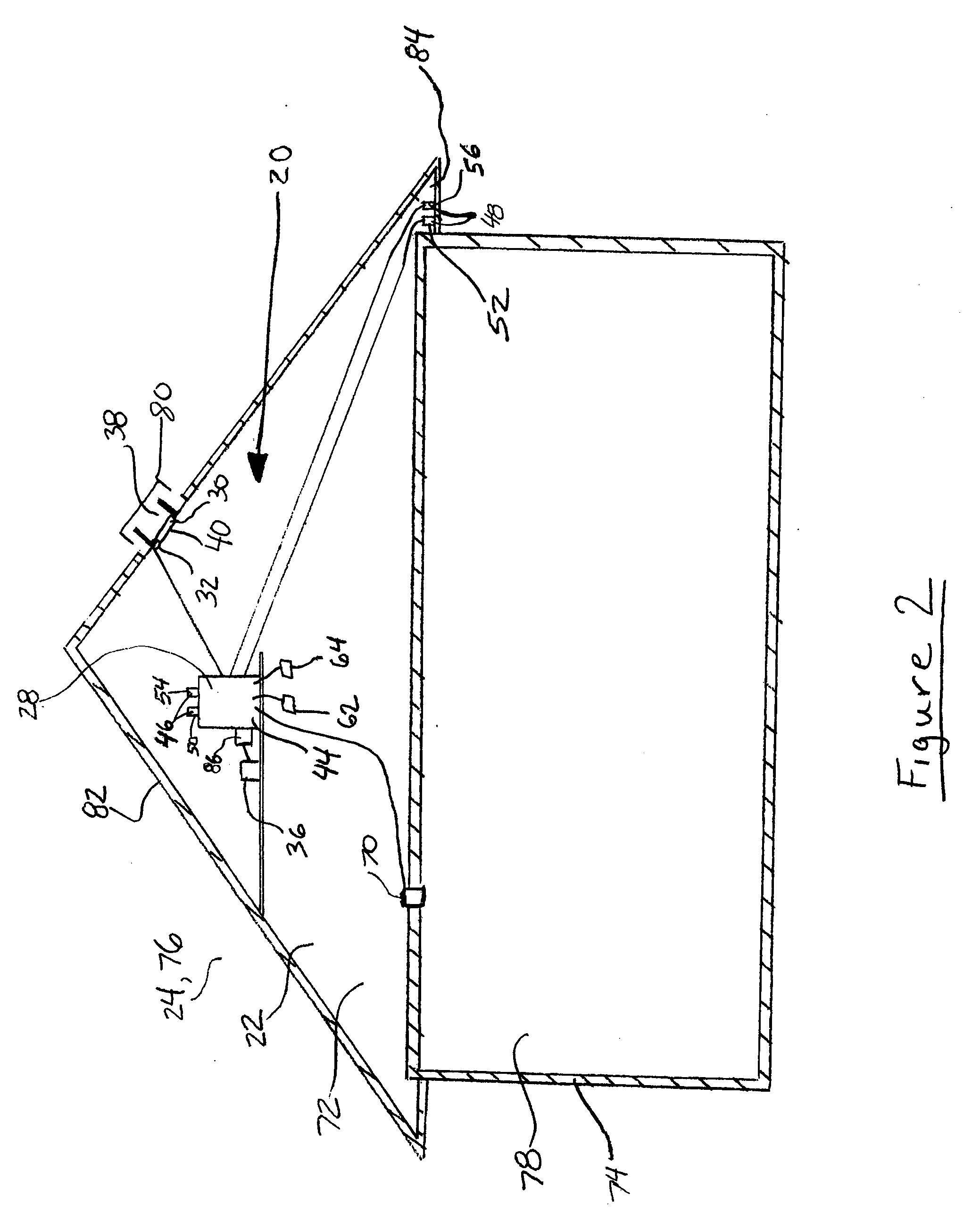
[0037] In a first embodiment, as shown in FIG. 1, the first space 22 is further defined as an attic 72 of a building 74, such as a residential or commercial building 74, and the second space 24 is further defined an exterior 76 of the building 74. The ventilation system 20 may be mounted in the attic 72 of a building 74. In such a configuration, the ventilation system 20 may regulate the temperature, humidity, and / or pressure of the attic 72 relative to the temperature, humidity, and / or pressure of the air of the exterior 76 of the building 74. The ventilation system 20 may be installed during the construction of a building 74 or may be installed to currently existing buildings 74. It should be appreciated that the ventilation system 20 is not limited to residential or commercial buildings 74, but may be mounted in any structure to control the temperature, humidity, and / or pressure of the interior 78 of the structure relative to the temperature and humidity of the air of the exterio...

second embodiment

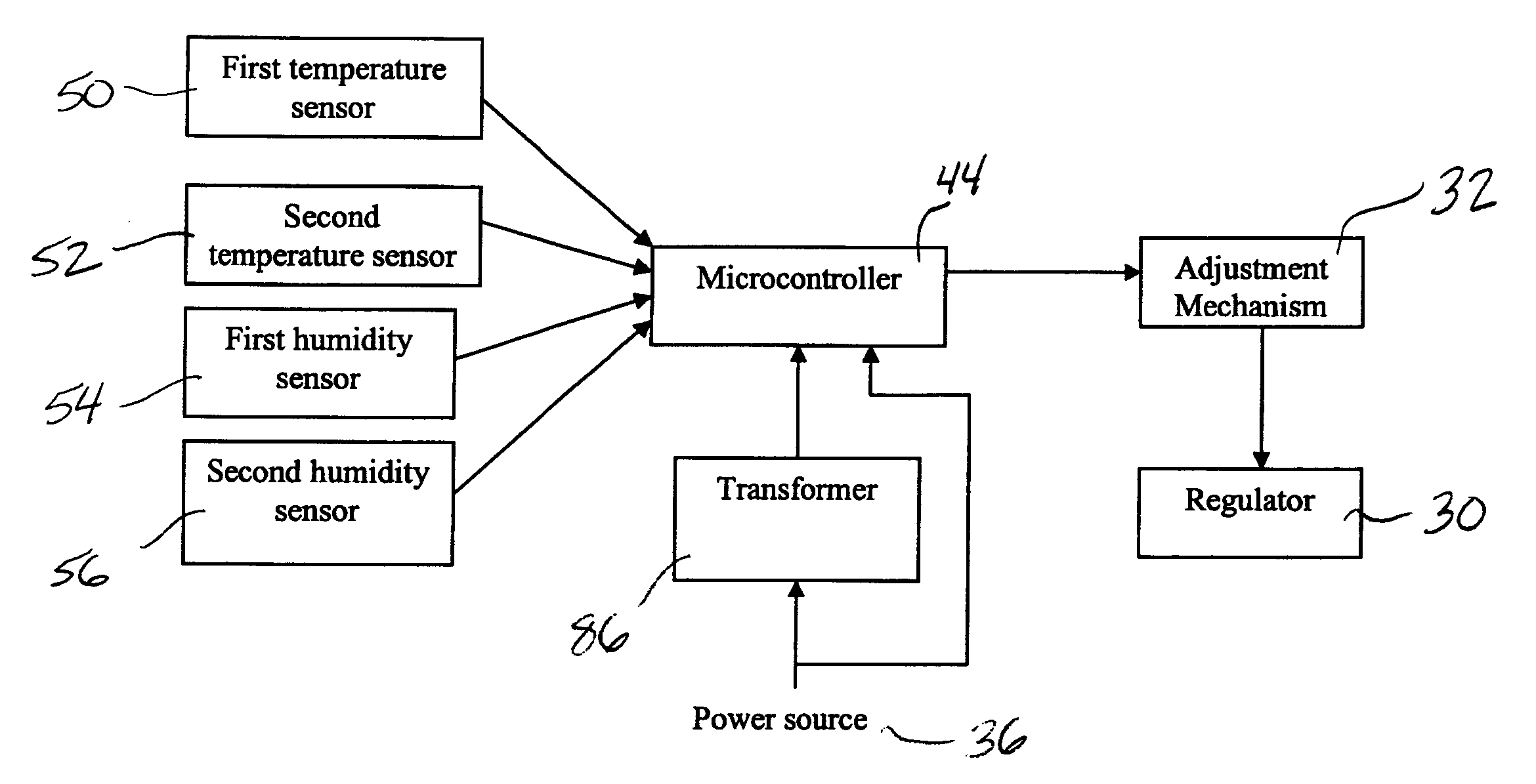
[0054] In the second embodiment, the microcontroller 44 may be connected by electrical wire to the regulator 30 and the sensors. Alternatively, the microcontroller 44 may communicate wirelessly with the regulator 30 and the sensors. The transformer 86 may be disposed between the power source 36 and the microcontroller 44 such that the transformer 86 provides a low voltage, e.g., 9V, to the microcontroller 44 to operate the microcontroller 44. The power source 36 may be, e.g., a 120V AC duplex outlet. The transformer 86 may be connected by electrical wire to the microcontroller 44. Alternatively, the microcontroller 44 may be directly connected to the power source 36.

[0055] The microcontroller 44 controls the regulator 30 depending upon the temperature of the air in the lower level 90 in relation to the temperature of the air of the upper level 88. For example, the microcontroller 44 may control electrical current supplied to the adjustment device such that the adjustment device adju...


PUM

PropertyMeasurementUnit
voltageaaaaaaaaaa
temperatureaaaaaaaaaa
humidityaaaaaaaaaa

Abstract

A ventilation system for regulating atmospheric communication between a first space and a second space includes an airflow regulation device and a control system. The airflow regulation device is disposed in fluid communication with the first and second spaces. The airflow regulation device includes a regulator for regulating airflow and an adjustment system connected to the regulator for adjusting the regulator. The control system includes a first sensor, a second sensor and a microcontroller. The first sensor is in fluid communication with the first space to measure a first atmospheric condition. The second sensor is disposed in fluid communication with the second space to measure a second atmospheric condition. The microcontroller is in communication with the first sensor and the second sensor for comparing the atmospheric conditions. The microcontroller is in communication with the adjustment system for adjusting the regulator in response to differences between atmospheric conditions.

Description

CROSS REFERENCE TO RELATED APPLICATION [0001] This application claims the benefit of U.S. Provisional Application Ser. No. 60 / 717,382 filed Sep. 15, 2005; U.S. Provisional Application Ser. No. 60 / 717,383 filed Sep. 15, 2005; and U.S. Provisional Application Ser. No. 60 / 597,129 filed Nov. 11, 2005, the entire specifications of all of which are expressly incorporated herein by reference.FIELD OF THE INVENTION [0002] The present invention generally relates to a ventilation system and a method of using the ventilation system. BACKGROUND OF THE INVENTION [0003] Traditionally, vents are mounted in a roof of a building and extend through the roof between an attic and an exterior of the building. The vents allow the flow of air between the attic and the exterior of the building to maintain a low temperature and a low humidity within the attic of the building. The low temperature of the air in the attic is important in winter months to prevent ice dams. In other words, if the temperature of ...

Claims


Application Information

Patent Timeline
Patent Type & Authority Applications(United States)
IPC IPC(8): F24F3/14B01F3/02F24F11/00B01F23/10
CPCF24F11/0001F24F11/0012F24F11/0015F24F2221/16F24F2011/0002F24F2011/0039F24F2011/0042F24F13/082F24F11/30F24F2110/10F24F2110/20F24F2110/32F24F2110/40
Inventor BYCZYNSKI, KENNETH C.POWELL, ROBERT A.
Owner BYCZYNSKI KENNETH C
Why Eureka
Try Eureka