Separable under load shaft coupling

a drive shaft and coupling technology, applied in the direction of couplings, mechanical equipment, transportation and packaging, etc., can solve the problems of rotors and two engines not being able to continue to fly to a safe landing, the driveshaft must be quickly disconnected, and the single point failure to achieve the effect of compromising flight safety

Inactive Publication Date: 2007-09-06
KAREM AIRCRAFT INC
View PDF41 Cites 26 Cited by
  • Summary
  • Abstract
  • Description
  • Claims
  • Application Information

AI Technical Summary

Problems solved by technology

However, while various advantages can be realized with such airplanes, tilt rotor aircraft, tilt wing aircraft and compound helicopters with two rotors and two engines cannot continue flight to a safe landing when a rotor (not an engine) fail, especially during hover and conversion to forward flight.
However, in emergencies where the rotor is the failure point, the driveshaft must be quickly disconnected regardless of the load on the driveshaft.
Still further, in order to render tilt-rotor and tilt-wing aircraft acceptable for large scale transportation of passengers, it must be possible to continue flight to a safe landing with a damaged or disabled rotor, and not allow such single-point failure to unduly compromise flight safety.
Unfortunately, as the scale of the machinery increases, and the power and torque increase (e.g., to and above several thousand foot pounds), plate clutches

Method used


Image

  • Separable under load shaft coupling
  • Separable under load shaft coupling
  • Separable under load shaft coupling

Examples


Embodiment Construction

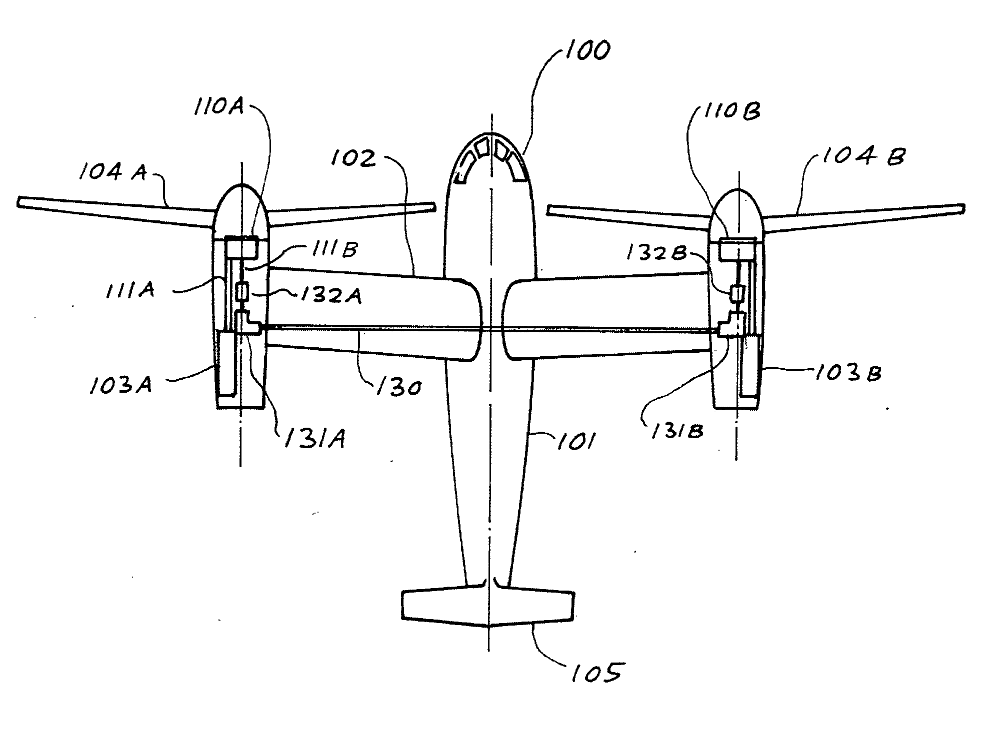
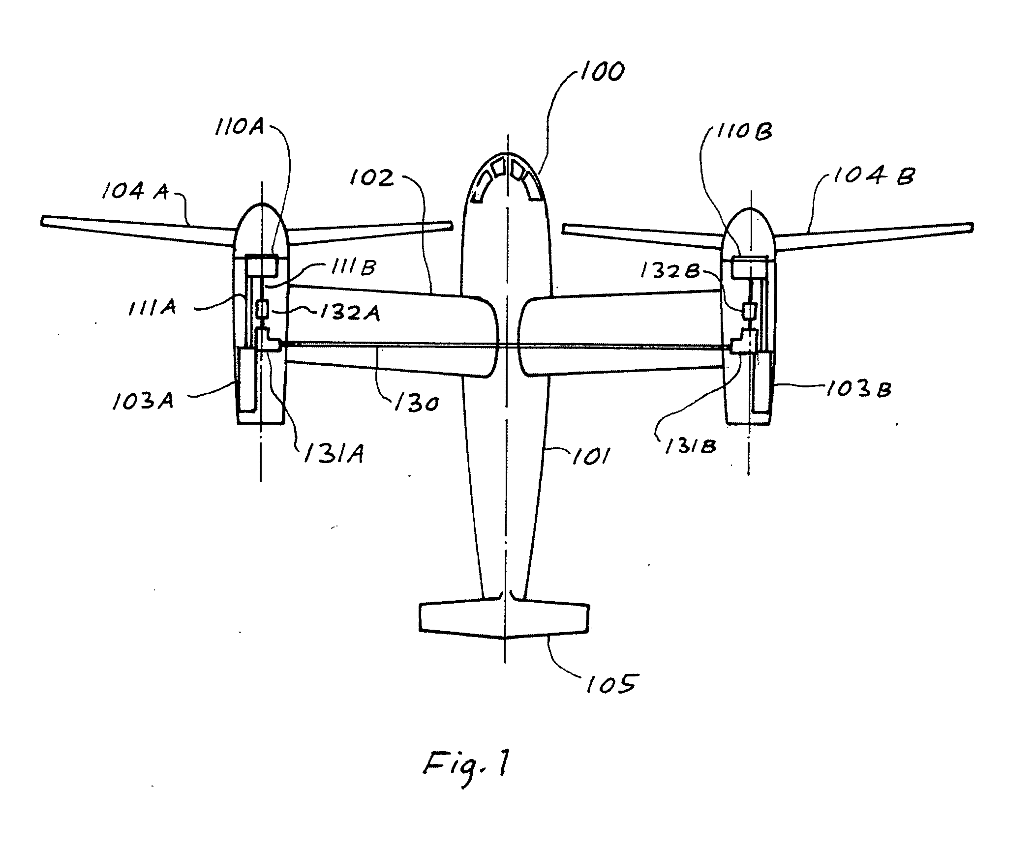
[0014] A typical tilt rotor aircraft is depicted in FIG. 1 in which rotorcraft 100 includes fuselage 101, a transverse wing 102, tail 105, left and right engines 103A and 103B, with left and right rotors 104A and 104B, respectively. Left and right gearboxes 110A and 110B are rotatably coupled via cross-wing drive shaft 130, angle drives 131A and 131B, and separable under-load couplings 132A and 132B. Shafts 111A and 111B transmit power from the engines to the rotors.

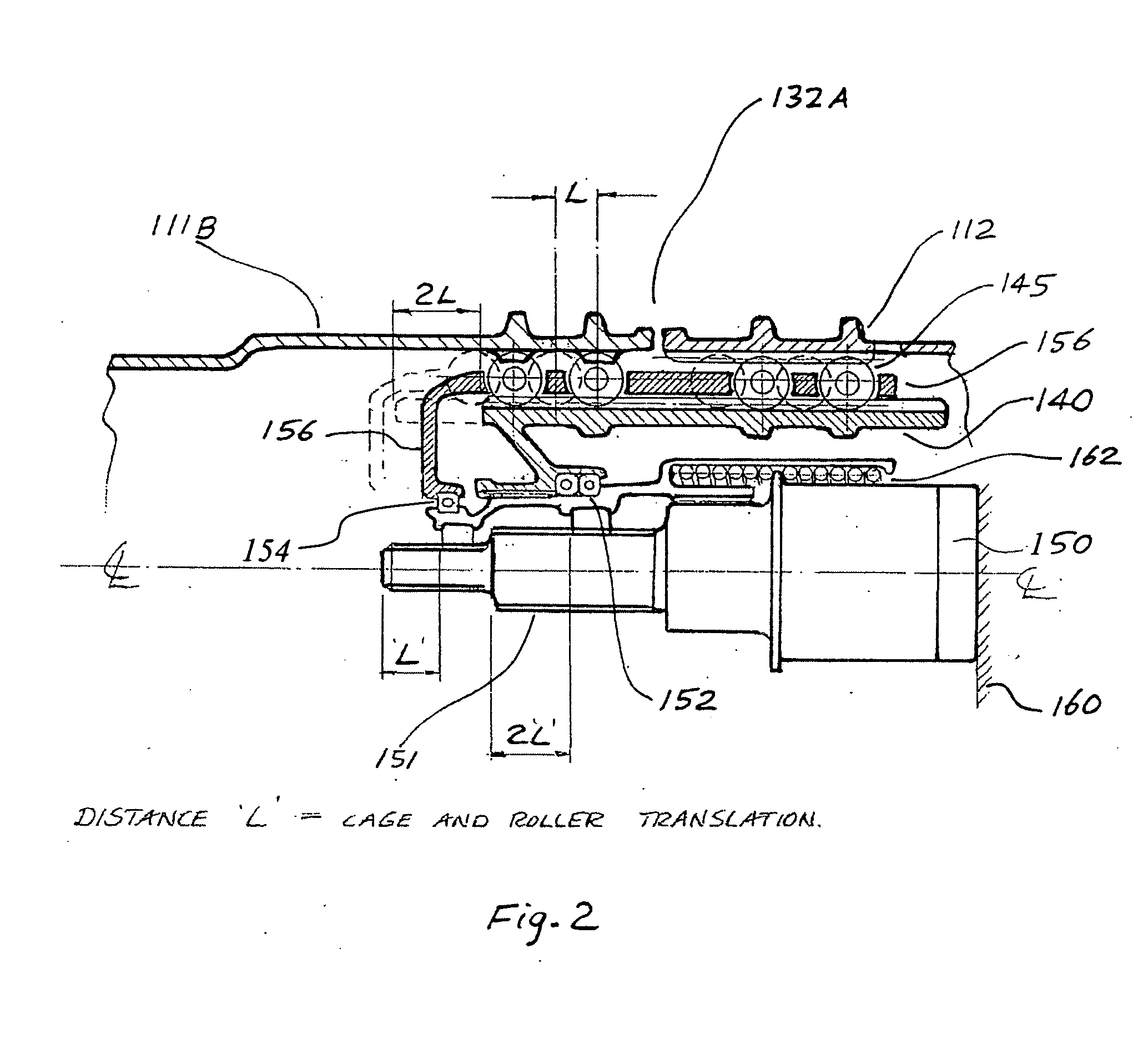
[0015] In rotorcraft or fixed wing aircraft with more than one rotor or propeller, continued flight is often possible with a single rotor. But, unless there are multiple power sources, it is necessary to disable and disconnect the damaged rotor or propeller from the power source. And it is necessary to do that quickly, and under load. Couplings as contemplated herein can be used for that purpose. In especially preferred embodiments, significant torque capacity can be achieved by utilizing many rollers, with each roller ...


PUM


Abstract

Contemplated couplings include an intermediate shaft internal and coaxial to a driver and a driven shaft, wherein the intermediate shaft moves a plurality of teethed rollers that engage with corresponding splined inner surfaces of the driver and the driven shaft. Such devices allow separation of the shafts under load using substantially reduced force and will typically have a friction coefficient virtual μ of less than 0.05.

Description

[0001] This application claims the benefit of our U.S. provisional patent application with the serial No. 60 / 693722, which was filed Jun. 24, 2005.FIELD OF THE INVENTION [0002] The field of the invention is drive couplings. BACKGROUND OF THE INVENTION [0003] Multi rotor aircraft, and especially tilt rotor aircraft and compound helicopters provide unique capabilities and have become increasingly attractive. However, while various advantages can be realized with such airplanes, tilt rotor aircraft, tilt wing aircraft and compound helicopters with two rotors and two engines cannot continue flight to a safe landing when a rotor (not an engine) fail, especially during hover and conversion to forward flight. [0004] Therefore, most such aircraft employ a cross-wing driveshaft that couples the left rotor to the right rotor to provide backup actuation for hover and VTOL. Moreover, the cross-wing drive shaft can also be used to provide power in forward flight in the event of an engine failure...

Claims


Application Information

Patent Timeline
IPC IPC(8): B64D35/00
CPCB64D35/04F16D3/065F16C3/035F16C2326/43
Inventor WAIDE, WILLIAM MARTIN
Owner KAREM AIRCRAFT INC
Why Eureka
Try Eureka