Network enabled radiation detection systems, methods of monitoring radiation, and network enabled radiation monitoring systems

a radiation detection system and radiation monitoring technology, applied in signalling systems, fire alarms, instruments, etc., can solve the problems of sensitivity of detectors to gamma rays, difficult for such detectors to distinguish between gamma rays and neutrons,

Inactive Publication Date: 2007-09-06
BATTELLE ENERGY ALLIANCE LLC
View PDF11 Cites 29 Cited by
  • Summary
  • Abstract
  • Description
  • Claims
  • Application Information

AI Technical Summary

Problems solved by technology

While radiation detectors for detecting high energy photons (e.g., gamma rays) and high energy particles (e.g., neutrons) exist and are being used, they are not without their problems.
For example, a problem with prior art neutron detectors relates to the sensitivity of the detectors to gamma rays.
Consequently, it is difficult for such detectors to discriminate (i.e., differentiate) between gamma rays and neutrons.
Since both gamma and neutron radiation must be separately measured in order to accurately measure the radiation field, such neutron detectors are not particularly useful in accurately characterizing the radiation field.
While such dual detector systems are known and have been used, they tend to be bulky, heavy, and difficult to carry.
In addition, such devices tend to consume a fair amount of electrical power, thus limiting their usefulness, particularly in portable applications.
While smaller, more portable detectors exist, they are typically only responsive to one type of radiation.
Consequently, film badges can only provide after-the-fact information, which can have tragic consequences in cases of acute radiation exposure.
Consequently, there remains a need for a radiation detection system that is capable of detecting and measuring both gamma radiation and neutron radiation, but yet is small and compact enough to be considered truly portable.

Method used


Image

  • Network enabled radiation detection systems, methods of monitoring radiation, and network enabled radiation monitoring systems
  • Network enabled radiation detection systems, methods of monitoring radiation, and network enabled radiation monitoring systems
  • Network enabled radiation detection systems, methods of monitoring radiation, and network enabled radiation monitoring systems

Examples


Embodiment Construction

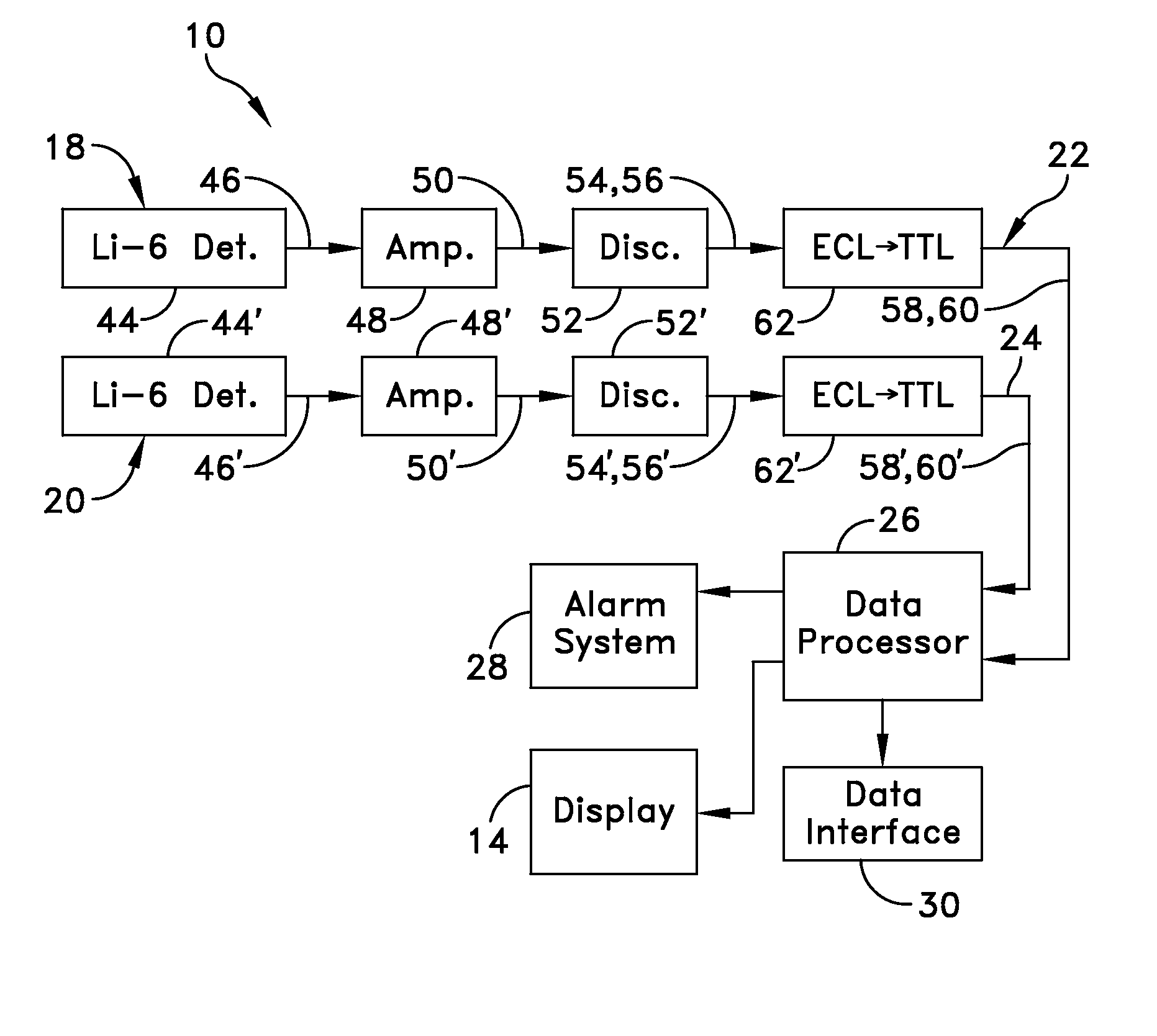
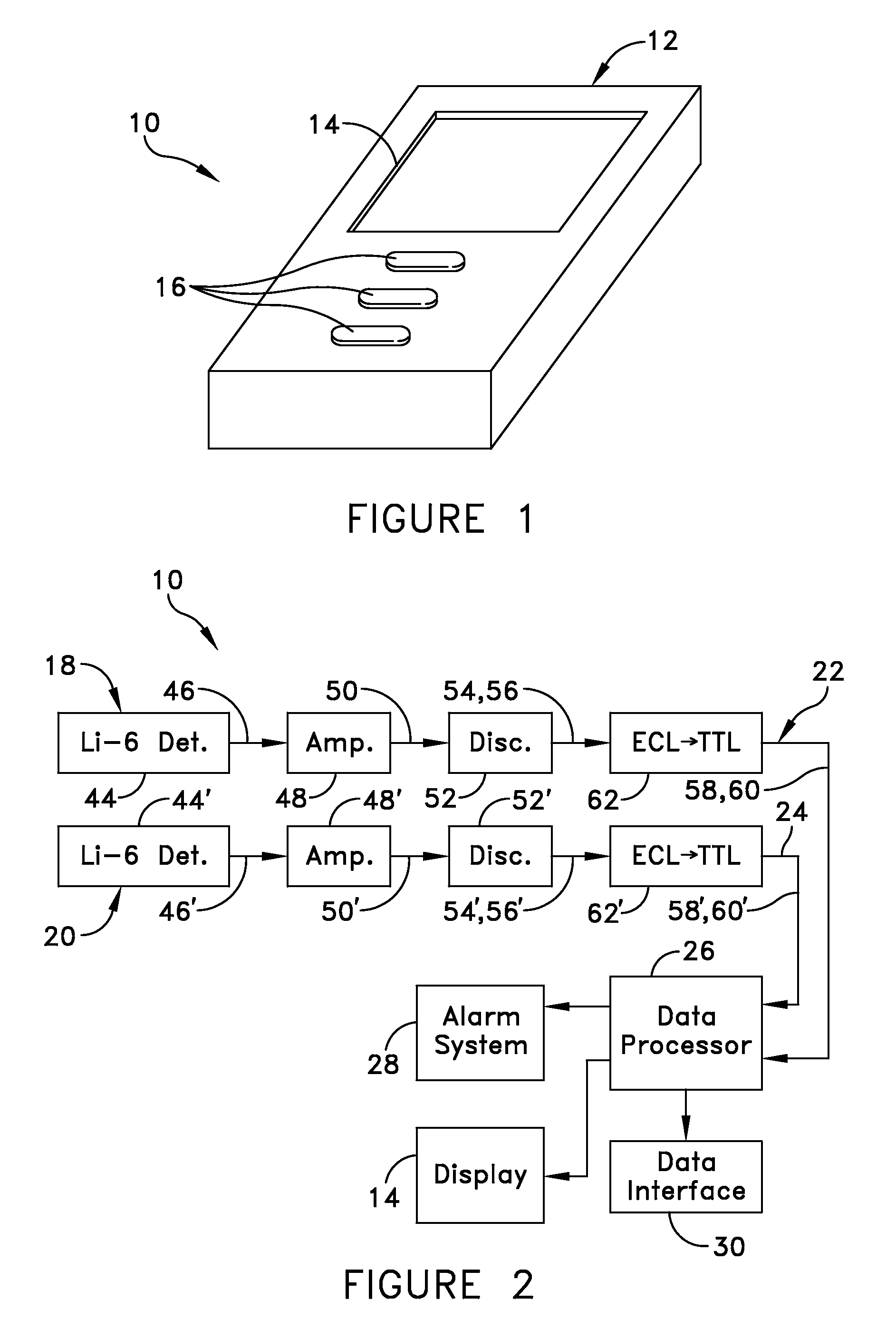
[0033] A radiation detection system 10 according to one embodiment of the present invention is best seen in FIGS. 1 and 2 and may comprise a small, palm-sized housing 12 sized to receive the various internal components and systems of the radiation detection system 10. The housing 12 may be provided with a display device 14, such as a liquid crystal display, for displaying the measured radiation levels as well as for displaying various information and data relating to the operation of the detection system. In addition, the housing 12 may be provided with one or more selection switches or buttons 16 to allow the user (not shown) to control the function and operation of the radiation detection system 10 in the manner that will be more fully described below. While the housing 12 of the radiation detection system 10 is configured to be hand-held, the housing 12 also may be provided with a suitable clip or bracket (not shown) to allow the user to secure the device to his person (e.g., via...


PUM


Abstract

A network enabled radiation detection system includes a sensor configured for measuring radiation; a microprocessor configured for receiving data from the sensor related to radiation; memory operatively associated with the microprocessor; software code configured for time stamping data related to radiation, and for storing data, subsequent to time stamping, in the memory; and wireless communication equipment configured for transmitting a message with the data related to radiation to another device. A method of monitoring radiation with a network enabled radiation detection system includes measuring radiation with a sensor; receiving data into a microprocessor related to the radiation; time stamping the data related to radiation; storing the data in memory; and transmitting the data to a base station.

Description

CROSS-REFERENCE TO RELATED APPLICATION [0001] This is a continuation-in-part of co-pending U.S. patent application Ser. No. 10 / 687,466, filed on October 15, 2003, entitled “Method and Apparatus for Detecting Neutrons and Gamma Rays” which is a continuation-in-part of U.S. patent application Ser. No. 09 / 742,964, filed on Dec. 20, 2000, entitled “Real Time Neutron and Gamma Ray Dosimeter,” (now abandoned), both of which are hereby incorporated herein by reference for all that they disclose.GOVERNMENT RIGHTS [0002] This Invention was made under a Cooperative Research and Development Agreement between View Systems, Inc. and Battelle Energy Alliance, LLC under Contract No. DE AC05ID14517, awarded by the U.S. Department of Energy. The U.S. Government has certain rights in the invention.TECHNICAL FIELD [0003] This invention relates to radiation detectors in general and more specifically to radiation detectors for providing real-time radiation data. BACKGROUND OF INVENTION [0004] Radiation ...

Claims


Application Information

Patent Timeline
Patent Type & Authority Applications(United States)
IPC IPC(8): G08B1/08G08B17/12
CPCG01T1/17
Inventor SPENCER, DAVID F.ARYAEINEJAD, RAHMAT
Owner BATTELLE ENERGY ALLIANCE LLC
Why Eureka
Try Eureka