Ambient gas compensation in an optical system

a technology of optical system and ambient environment, applied in the field of optical sensing techniques and apparatuses, can solve the problems of eliminating the material of interest, existing technologies do not account for the possibility of the presence of a material of interest in the ambient environment around or within the monitor,

Active Publication Date: 2010-04-27
PHILIPS RS NORTH AMERICA LLC
View PDF7 Cites 6 Cited by
  • Summary
  • Abstract
  • Description
  • Claims
  • Application Information

AI Technical Summary

Benefits of technology

[0010]Without limiting its scope, the present invention includes optical sensors that are configured to compensate for the possible presence of a material of interest in the ambient environment through which monitoring radiation passes, optical sensors that eliminate the possibility of a material of interest in the ambient environment from interfering with monitoring radiation, and methods for eliminating error introduced by a material of interest that is possibly present in the ambient environment into an optical measurement of the amount of the material of interest in a sample.

Problems solved by technology

Unfortunately, existing technologies do not account for the possible presence of a material of interest in the ambient environment around or within a monitor, or eliminate the material of interest from the ambient environment around or within the monitor.

Method used


Image

  • Ambient gas compensation in an optical system
  • Ambient gas compensation in an optical system
  • Ambient gas compensation in an optical system

Examples


Embodiment Construction

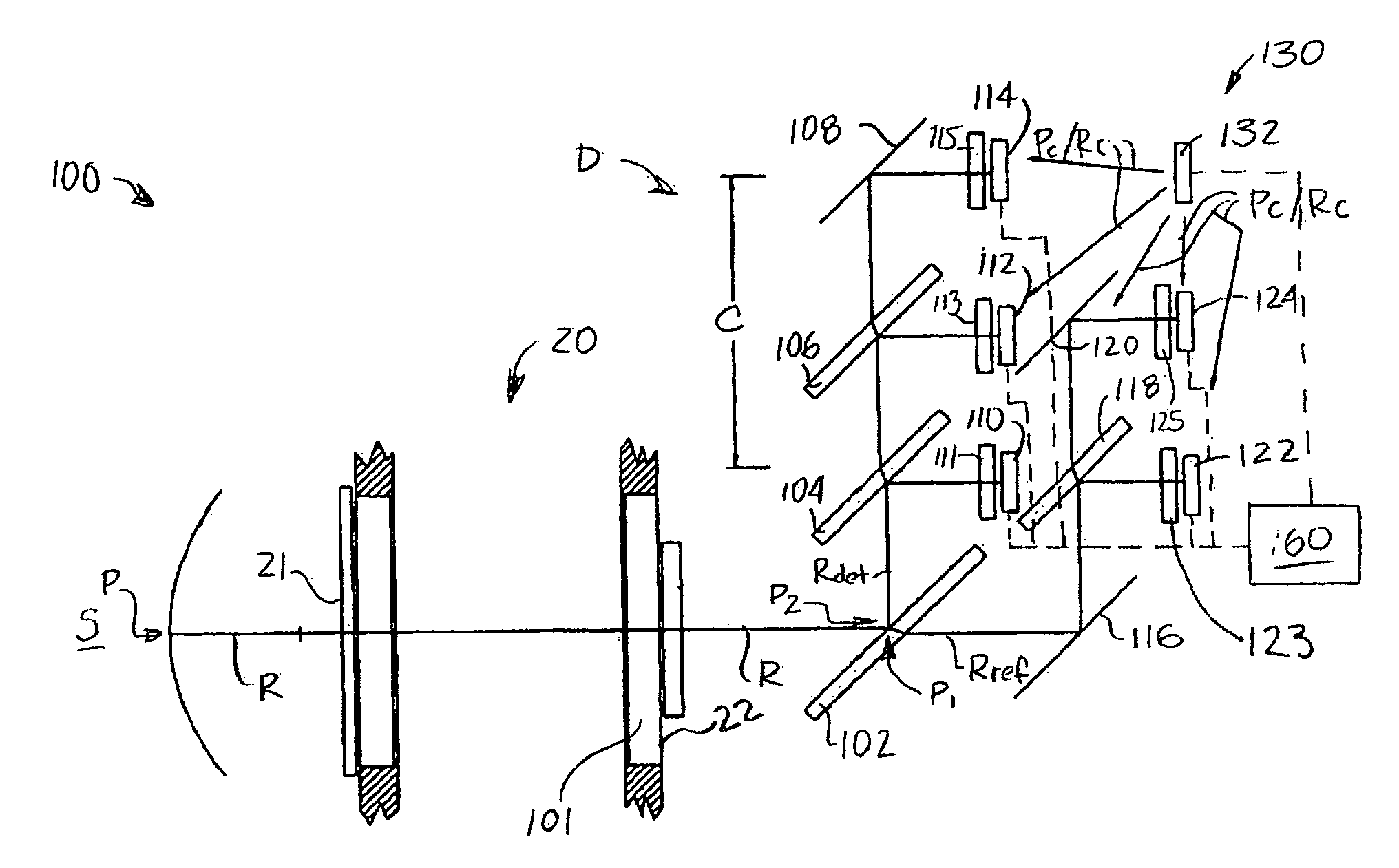
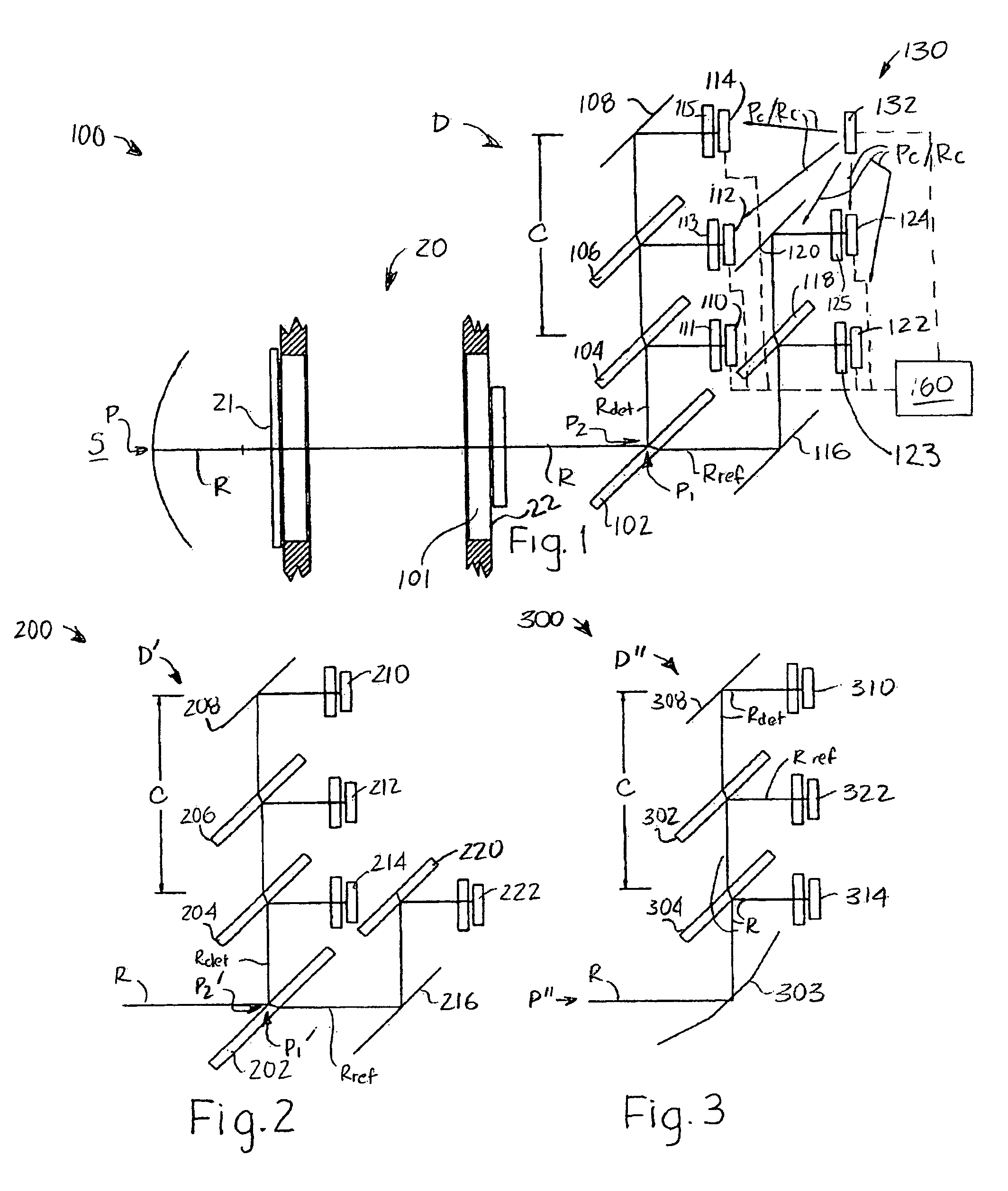
[0019]FIG. 1 illustrates a first example of an embodiment of optical sensor 100 that incorporates teachings of the present invention. Optical sensor 100 includes a source S of electromagnetic radiation, which is configured to be positioned on one side 21 of a sample cuvette 20, as well as a detection system D configured to be positioned on another (e.g., the opposite) side 22 of sample cuvette 20. Optical sensor 100 may be used to detect one or more gaseous or vapor components of a sample. By way of nonlimiting example, optical sensor 100 may be configured to monitor carbon dioxide and nitrous oxide in a respiratory sample.

[0020]When optical sensor 100 is configured for monitoring carbon dioxide, nitrous oxide, or other materials that attenuate electromagnetic radiation in the infrared portion of the spectrum, source S may comprise a source of electromagnetic radiation R of one or more infrared wavelengths. Radiation R is emitted along a path P, which extends from source S to detect...


PUM


Abstract

An optical sensor is configured to determine an amount of at least one material in a sample without interference from any of the material of interest present in an ambient environment in which the optical sensing is effected. The optical sensor may include a compensation detector positioned a different distance apart from a source of monitoring radiation than the distance that a primary, measurement detector is positioned from the source. Alternatively, the optical sensor may include an optically transparent material that consumes space within the sensor and, thus, eliminates ambient amounts of a material of interest from at least a portion of an optical pathway through the sensor. A calibration element transmits calibration radiation to one or more detectors of an optical sensor to facilitate correction of any changes in the manner in which the one or more detectors sense radiation. Optical sensing methods are also disclosed, as are calibration methods.

Description

CROSS-REFERENCE TO RELATED APPLICATIONS[0001]This application claims priority under 35 U.S.C. §119(e) from provisional U.S. patent application No. 60 / 727,962 filed Oct. 18, 2005 the contents of which are incorporated herein by reference.BACKGROUND OF THE INVENTION[0002]1. Field of the Invention[0003]The present invention relates generally to optical sensing techniques and apparatus, and, more specifically, to techniques and apparatus for obtaining a measurement of at least one material in a sample that is substantially free of ambient gas.[0004]2. Description of the Related Art[0005]Optical sensors have long been used to measure the amount of one or more gases in a sample of interest. Optical sensors have been used in a variety of environments, including respiratory gas monitoring. The operation of many optical sensors is based upon a scientific principle known as “absorbance” or “attenuation” of electromagnetic radiation, such as light or infrared radiation.[0006]The wavelengths of...

Claims


Application Information

Patent Timeline
Patent Type & Authority Patents(United States)
IPC IPC(8): G01J5/02
CPCG01J3/42G01N21/274G01N21/314G01N2021/3166G01N21/3504G01N2021/3137
Inventor RUSSELL, JAMES T.
Owner PHILIPS RS NORTH AMERICA LLC
Why Eureka
Try Eureka