
Image forming apparatus and image forming method

a technology of image forming apparatus and forming method, which is applied in the direction of electrographic process apparatus, instruments, optics, etc., can solve the problems of smudges on the back of sheet paper or images, inability to obtain the bias voltage necessary for recovering the toner adhered on the transfer member to the image bearing member, and smudging the surface of the transfer member, so as to achieve a high-quality toner image and prevent smudges on the back of recording

Active Publication Date: 2007-09-06
KK TOSHIBA +1
View PDF6 Cites 14 Cited by
  • Summary
  • Abstract
  • Description
  • Claims
  • Application Information

AI Technical Summary

Benefits of technology

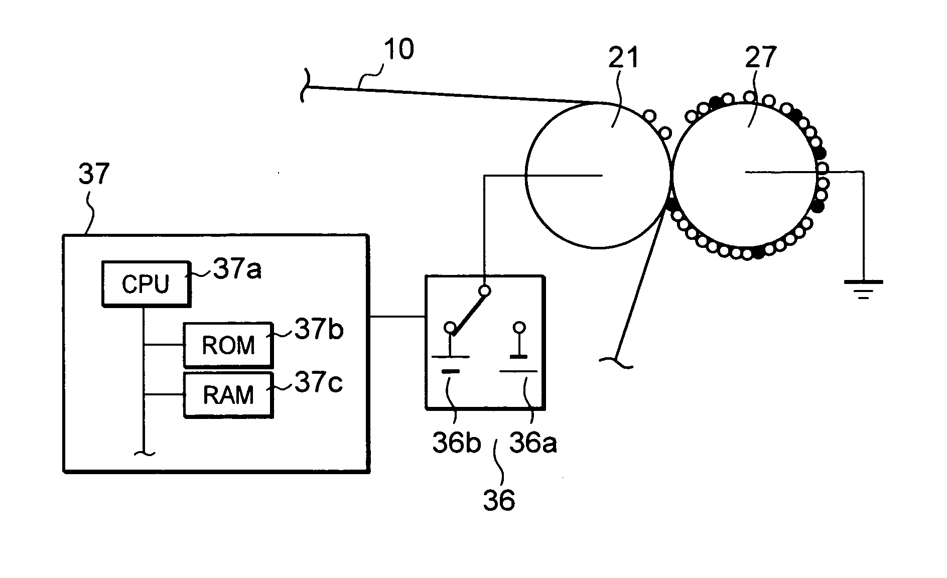
[0009] According to an aspect of the invention, there is provided an image forming apparatus that passes a recording medium between an image bearing member and a transfer member to thereby transfer toner images on the image bearing member onto the recording medium, in which toner adhered to the transfer member is recovered to the image bearing member without fail. With this arrangement, smudges on the back of the recording medium or images are prevented, thereby ensuring a high-quality toner image.

Problems solved by technology

However, in this transfer system, without sheet paper between the image bearing member and the transfer member, the transfer member comes into direct contact with the image bearing member to cause the toner to adhere to the transfer member, smudging the surface of the transfer member.
Accordingly, there is the possibility that a bias voltage necessary for recovering the toner adhered on the transfer member to the image bearing member cannot be obtained even when the bias voltage is controlled according to the measurements by the temperature and humidity sensor.
Accordingly, the toner adhered on the surface of the transfer member may not be sufficiently recovered, causing smudges on the back of sheet paper or images.

Method used


Image

  • Image forming apparatus and image forming method
  • Image forming apparatus and image forming method
  • Image forming apparatus and image forming method

Examples


Embodiment Construction

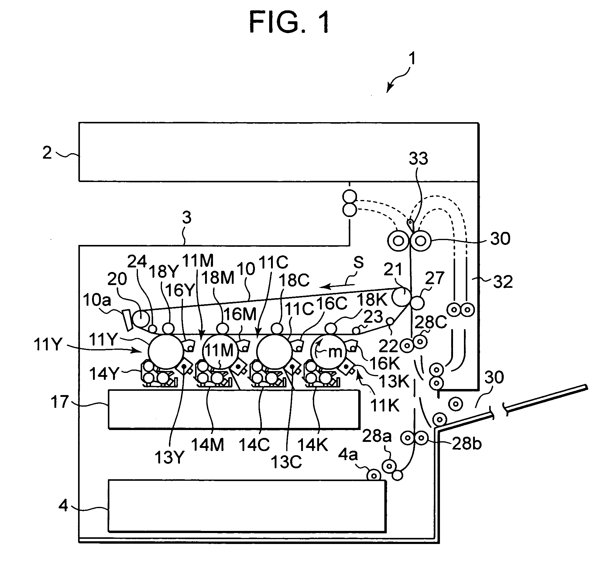
[0017] An embodiment of the invention will be specifically described with reference to the accompanying drawings. FIG. 1 is a schematic diagram of a color copying machine 1 of a four-connection tandem system, which is an image forming apparatus according to an embodiment of the invention. The color copying machine 1 includes a scanner 2 and an in-machine output section 3 at the upper part. The color copying machine 1 also includes four image forming units 11Y, 11M, 11C, and 11K of yellow (Y), magenta (M), cyan (C), and black (K) which are juxtaposed along the lower side of an endless intermediate transfer belt 10.

[0018] The image forming units 11Y, 11M, 11C, and 11K have photoconductor drums 12Y, 12M, 12C, and 12K of a diameter of 30 mm, respectively. Around each of the photoconductor drums 12Y, 12M, 12C, and 12K, there are disposed chargers 13Y, 13M, 13C, and 13K, developer units 14Y, 14M, 14C, and 14K, and photoconductor-drum cleaning units 16Y, 16M, 16C, and 16K, respectively, i...


PUM


Abstract

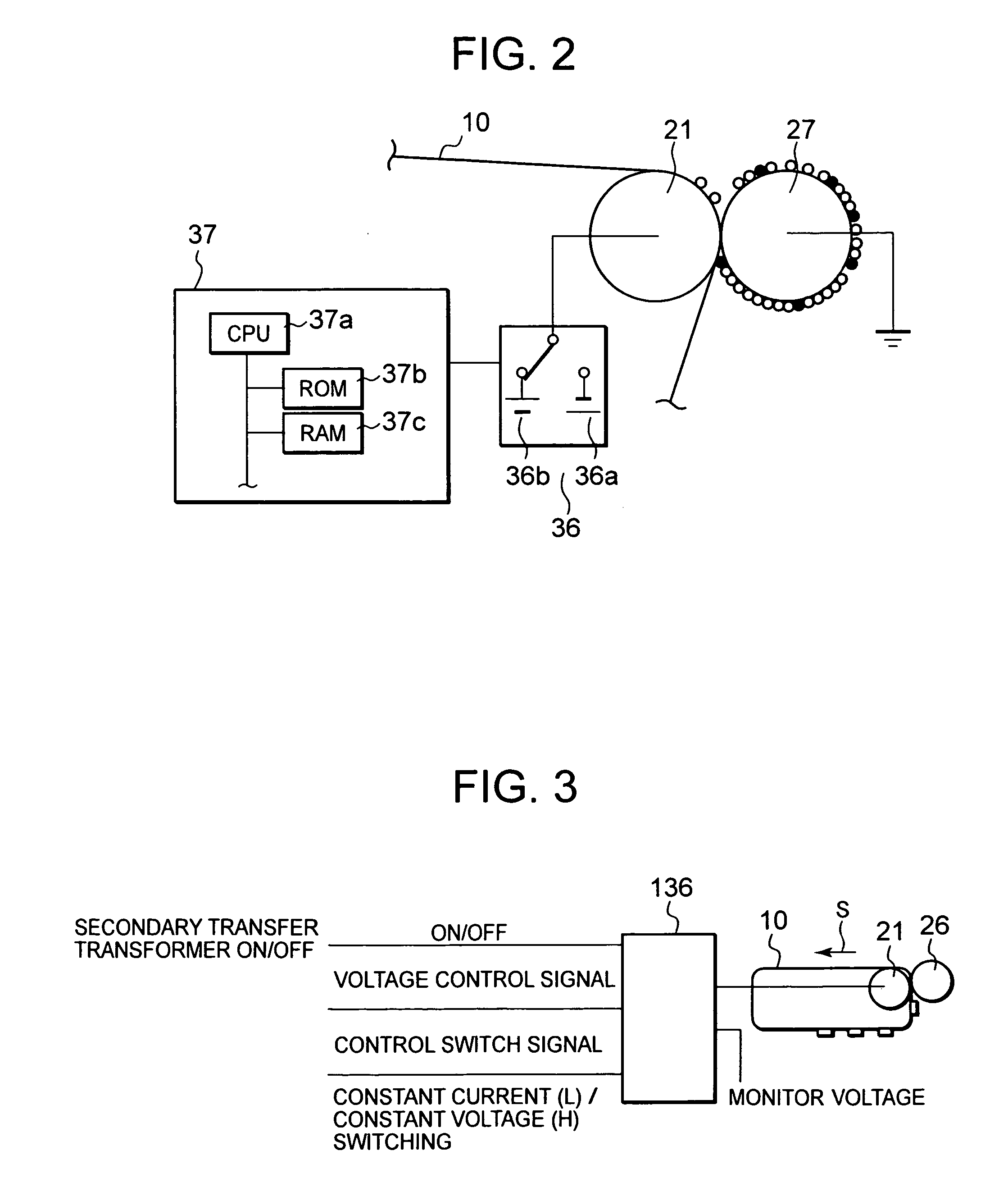
According to the invention, a constant current output is applied to a backup roller or a secondary transfer member, and the cleaning bias is controlled according to the measurement obtained by monitoring the voltage generated at that time. Cleaning biases of a plus polarity and a minus polarity are alternately applied to the backup roller to recover the toner adhered on the secondary transfer roller to the intermediate transfer belt. The cleaning bias is controlled according to the combined resistance of the secondary transfer section which is varied with not only the environment of the image forming apparatus, but also the condition of use and various factors to recover the toner adhered to the secondary transfer roller to the intermediate transfer belt without fail, thereby preventing smudges on the back of sheet paper or smudges on images.

Description

BACKGROUND OF THE INVENTION [0001] 1. Field of the Invention [0002] The present invention relates to image forming apparatuses for use in electrophotographic copying machines and color printers, in which the toner adhered to transfer members is removed. [0003] 2. Description of the Related Art [0004] Some of image forming apparatuses of copying machines and printers have a transfer member that comes into contact with an opposed image bearing member to transfer toner images formed on the image bearing member. The apparatuses pass sheet paper between the image bearing member and the transfer member, and form an electric field between the image bearing member and the transfer member to transfer the toner image on the image bearing member onto the sheet paper. [0005] However, in this transfer system, without sheet paper between the image bearing member and the transfer member, the transfer member comes into direct contact with the image bearing member to cause the toner to adhere to the...

Claims


Application Information

Patent Timeline
Patent Type & Authority Applications(United States)
IPC IPC(8): G03G15/16
CPCG03G15/0131G03G2215/0119G03G15/161
Inventor IZUMI, TAKAOOGASAWARA, MASATO
Owner KK TOSHIBA
Learn More