
Cartridge accommodation case

a technology for cartridges and housing cases, applied in the field of cartridge housing cases, can solve the problems of low convenience, low resistance, and low b>1/b> wetness, and achieve the effects of high stackability, high efficiency of housing work, and sufficient resistance to impa

Inactive Publication Date: 2007-09-13
FUJIFILM CORP
View PDF6 Cites 4 Cited by
  • Summary
  • Abstract
  • Description
  • Claims
  • Application Information

AI Technical Summary

Benefits of technology

[0009] The present invention has been made in view of the above circumstances, and an object of the invention is therefore to provide a cartridge accommodation case capable of realizing high efficiency of housing work and high stackability (stacked cases are stable and do not collapse) while securing sufficient resistance to impact.
[0017] In the cartridge accommodation case of the second preferable embodiment of the invention, the ribs provided in the top case and the ribs provided in the bottom case are in a fitting relationship of a convex portion and a concave portion. Therefore, the ribs can easily be fitted into / with each other and are not easily disengaged from each other.

Problems solved by technology

However, in this accumulated packing, since cartridges 1 are accommodated in a corrugated cardboard box 5, to check the presence / absence, types, etc. of cartridges 1 it is necessary to open the corrugated cardboard box 5, which is low in convenience.
Another problem is that in the event of flooding a corrugated cardboard box 5 which is packed with cartridges 1 becomes wet and may be broken.
Therefore, in actual housing work, cartridges 1 are put into the case 7 one by one, which is inconvenient particularly in the case where a large number of cartridges 1 need to be stored.
This raises a problem that the case 7 is low in the resistance to impact and hence in the ability to absorb impact when the case 7 is dropped.
Still further, when cases 7 are stacked in the vertical direction, they are rendered unstable because they are not formed with proper ribs.

Method used


Image

  • Cartridge accommodation case
  • Cartridge accommodation case
  • Cartridge accommodation case

Examples


Embodiment Construction

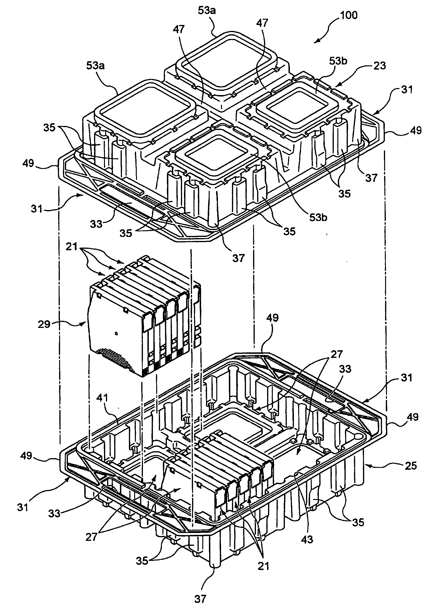
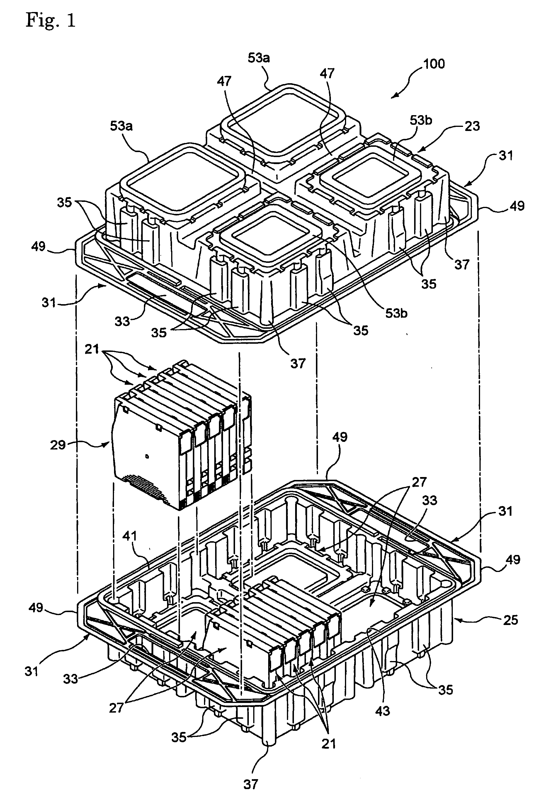
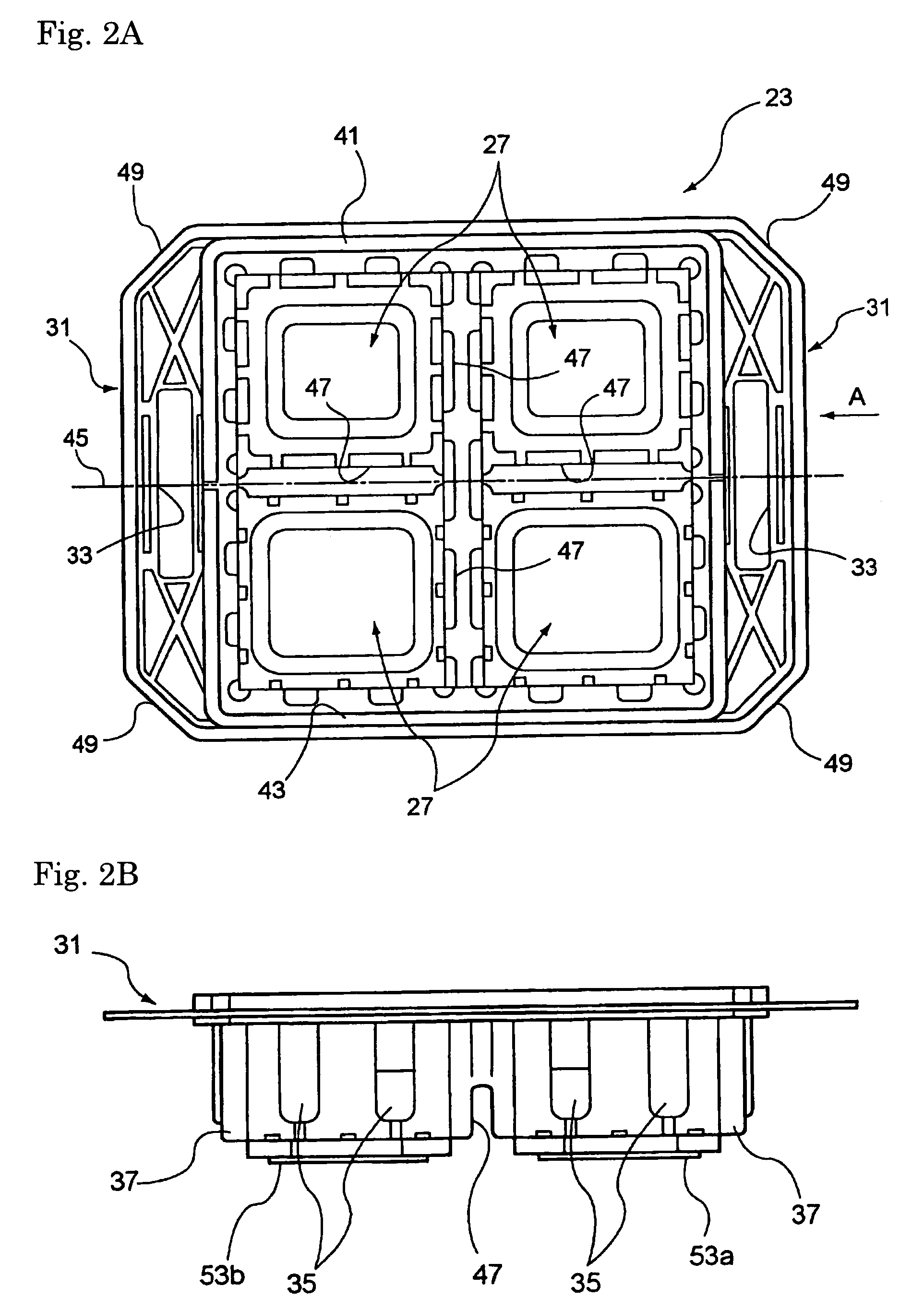
[0029] A cartridge accommodation case according to a preferred embodiment of the present invention will be hereinafter described in detail with reference to FIGS. 1 to 7.

[0030]FIG. 1 is an exploded perspective view of the cartridge accommodation case to which the invention is directed in a state that it separated into a top case and a bottom case. FIGS. 2A and 2B are a plan view and a side view, respectively, of the bottom case shown in FIG. 1. FIGS. 3A and 3B shows the cartridge accommodation case in which FIG. 3A is a side view as viewed from the direction indicated by arrow A in FIG. 2A and FIG. 3B shows an appearance of an important part of the cartridge accommodation case, more specifically, buffer ribs formed in the outer wall of a partitioned room.

[0031] For example, the cartridge accommodation case 100 can be used suitably for housing flat-body-shaped cartridges 21 each of which incorporates a magnetic tape reel.

[0032] Each cartridge 21 incorporates the magnetic tape reel...


PUM


Abstract

A cartridge accommodation case includes a generally rectangular cartridge accommodation top case formed with partitioned rooms for holding plural cartridges and a generally rectangular cartridge accommodation bottom case having partitioned rooms which have substantially the same shape as and opposed to the partitioned rooms of the top case. The top case and the bottom case have the same structure and are provided with projections and recesses which can engage each other. The cartridge accommodation case is given, inside, partitioned rooms which are two times larger in space than the partitioned rooms of the top case and the bottom case when the top case and the bottom case are placed one on the other and the projections and the recesses are engaged with each other. The top case and the bottom case are provided with ribs which are fitted into / with each other when cartridge accommodation cases are stacked.

Description

FIELD OF THE INVENTION [0001] The present invention relates to a cartridge accommodation case (accommodation box) for accommodating flat-body-shaped cartridges each of which incorporates a magnetic tape reel. More particularly, the invention relates to a cartridge accommodation case which enables stable stacking of cartridge accommodation cases. BACKGROUND OF THE INVENTION [0002] Conventionally, to pack one-reel-type magnetic recording tape cartridges together, as shown in FIG. 8, one cartridge 1 is housed in each case 3 and plural cases 3 are packed in a corrugated cardboard box 5. Necessary buffering performance is thus attained. [0003] However, in this accumulated packing, since cartridges 1 are accommodated in a corrugated cardboard box 5, to check the presence / absence, types, etc. of cartridges 1 it is necessary to open the corrugated cardboard box 5, which is low in convenience. [0004] Another problem is that in the event of flooding a corrugated cardboard box 5 which is packe...

Claims


Application Information

Patent Timeline
Patent Type & Authority Applications(United States)
IPC IPC(8): B65D85/00
CPCG11B33/0438G11B23/0236
Inventor YUKAWA, MASAKI
Owner FUJIFILM CORP
Learn More