Electric motor and method of manufacturing the same

a technology of electric motors and motors, which is applied in the direction of machines/engines, positive displacement liquid engines, magnetic circuit shapes/forms/construction, etc., can solve the problems of increasing the vibration of the housing of rotating electric motors, hard to securely fit the stator core in the housing,

Inactive Publication Date: 2007-09-13
TOYOTA IND CORP
View PDF2 Cites 20 Cited by
  • Summary
  • Abstract
  • Description
  • Claims
  • Application Information

AI Technical Summary

Problems solved by technology

However, it is hard to securely fit the stator core in the housing so that the inner periphery of the housing is evenly join...

Method used


Image

  • Electric motor and method of manufacturing the same
  • Electric motor and method of manufacturing the same
  • Electric motor and method of manufacturing the same

Examples


Embodiment Construction

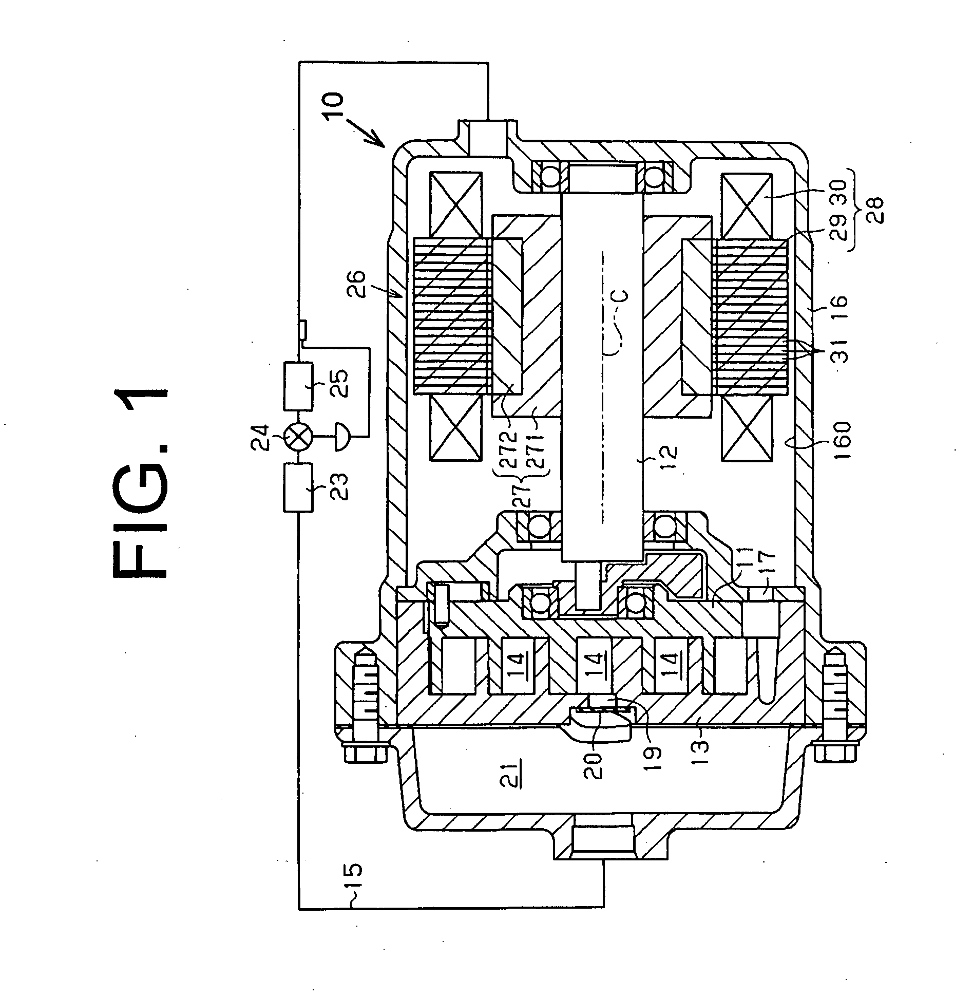
[0026]The following will describe a first preferred embodiment according to the present invention with reference to FIGS. 1 through 3. Referring to FIG. 1, a scroll type motor-driven compressor 10 has a movable scroll member 11 as a compression motion body, a fixed scroll member 13, an annular motor housing 16 as an annular housing and an electric motor 26 which includes a rotary shaft 12. The movable scroll member 11 is orbited as the rotary shaft 12 is rotated, thereby reducing the volume of compression chambers 14 between the movable and fixed scroll members 11 and 13. A refrigerant gas which is introduced from an external refrigerant circuit 15 into the motor housing 16 is drawn into the compression chamber 14 through a suction port 17. The refrigerant gas in the compression chamber 14 is discharged through a discharge port 19 into a discharge chamber 21 pushing open a discharge valve 20. The refrigerant gas in the discharge chamber 21 flows out of the compressor 10 to the exter...


PUM


Abstract

An electric motor includes an annular housing and an annular stator core having the inner periphery the shape of which differs from a perfect circle. The stator core is supported by the housing in such a manner that the outer periphery of the stator core and the inner periphery of the housing are partially in contact with each other. The inner periphery of the stator core is deformed to become close to the shape of the perfect circle when the stator core is securely fitted in the housing by shrink fitting.

Description

BACKGROUND OF THE INVENTION[0001]The present invention relates to an electric motor and a motor-driven compressor.[0002]Shrink fitting is used for securely fitting the stator core of an electric motor in a housing (cf. Japanese Patent Application Publication No. 2005-214160). Japanese Patent Application Publication No. 2005-214160 discloses that a particular relation between the inner diameter of the housing which is made of an aluminum-based material and fastening interference is set for securely fitting the stator core in the housing.[0003]However, it is hard to securely fit the stator core in the housing so that the inner periphery of the housing is evenly joined to the outer periphery of the stator core. For that purpose, it is preferable that a plurality of press-contact holding portions should be circumferentially provided on the inner periphery of the housing so as to contact with the outer periphery of the stator core, thereby holding the stator core, as disclosed in Japanes...

Claims


Application Information

Patent Timeline
IPC IPC(8): H02K9/00H02K5/00H02K1/00
CPCH02K1/185H02K1/16F04B39/00
Inventor FUKASAKU, HIROSHIMERA, MINORUSAEKI, AI
Owner TOYOTA IND CORP
Why Eureka
Try Eureka