Image transfer device for image forming apparatus

a transfer device and image technology, applied in the field of image forming apparatus, can solve the problems of unstable belt movement, unstable belt movement, unusable load and torque fluctuations, etc., and achieve the effect of effectively preventing the generation of warps in the transferred imag

Inactive Publication Date: 2007-09-13
RICOH KK
View PDF27 Cites 33 Cited by
  • Summary
  • Abstract
  • Description
  • Claims
  • Application Information

AI Technical Summary

Benefits of technology

[0026] An object of the present invention is to provide an image transfer device for an image forming apparatus of a type performing image transfer at nip positions of a primary transfer portion and secondary transfer portion employing an intermediate transfer member such ...

Problems solved by technology

However, because the seam of a seamed, endless belt protrudes therefrom, undesirable load and torque fluctuations attributable to this protruding section are generated as the belt is moved when the seam passes the primary transfer nip position and the secondary transfer nip position.
These fluctuations affect the movement of the belt and cause a change in the moving speed that leads to unstable belt movement.
On the other hand, when the front-end portion of the sheet serving as the recording medium P (particularly in the case of a thick sheet (extra thick paper)) goes into the secondary transfer nip position and the rear-end portion thereof comes out of the secondary transfer nip position, load and torque fluctuations attributable to the thickness of the recording medium P that which cause unstable belt movement occur.
Accordingly, warp leading to unsatisfactory image production is generated in the toner image transferred onto the sheet.
These include, for example, minute belt slip caused by load and torque fluctuations, belt stretching, deflection during rotation at the joint mechanism or gear portion serving as the decelerator mechan...

Method used


Image

  • Image transfer device for image forming apparatus
  • Image transfer device for image forming apparatus
  • Image transfer device for image forming apparatus

Examples


first embodiment

[0068] The description of this embodiment is based on a description of the prior art pertaining to this embodiment as given hereinafter with reference to the drawings.

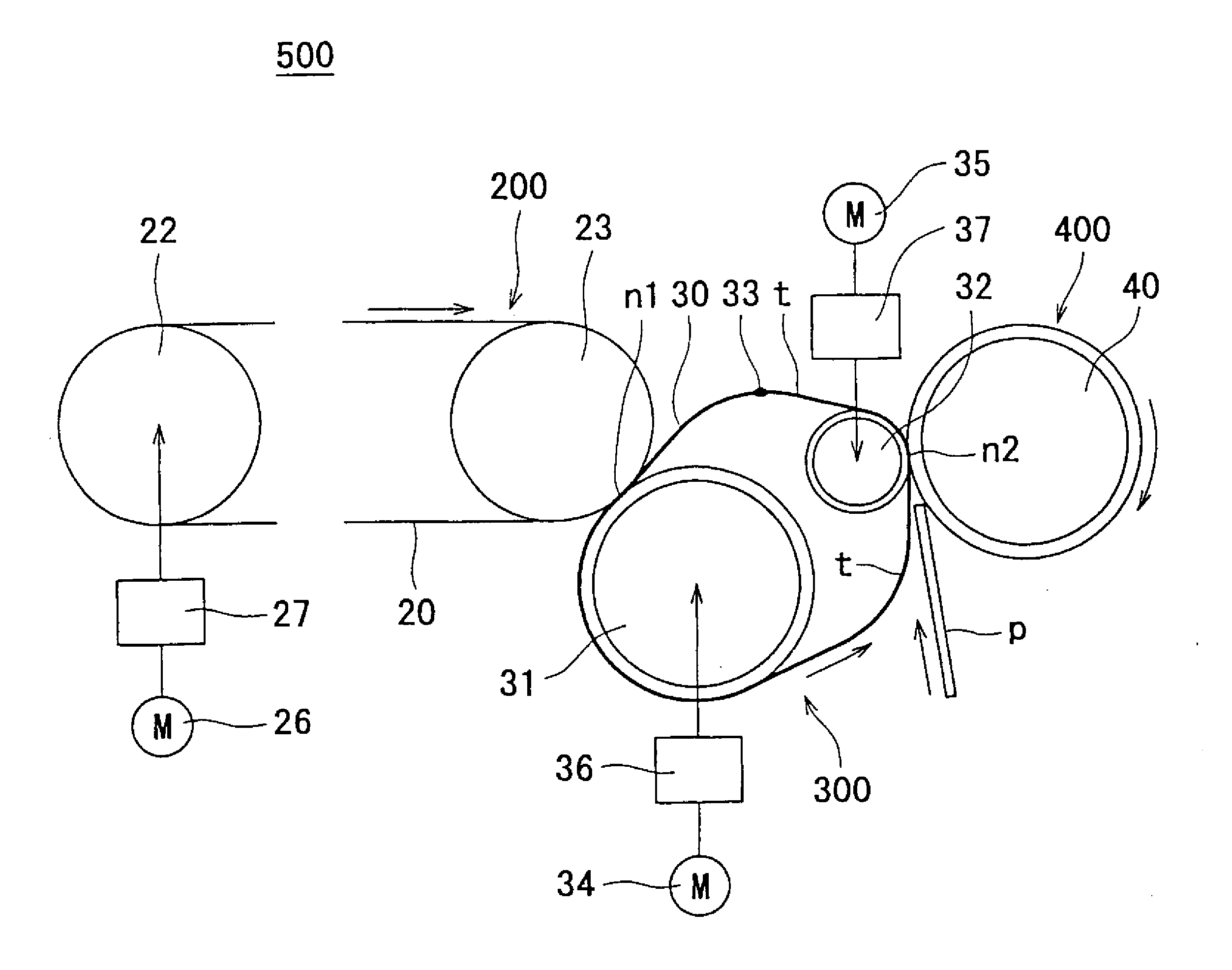
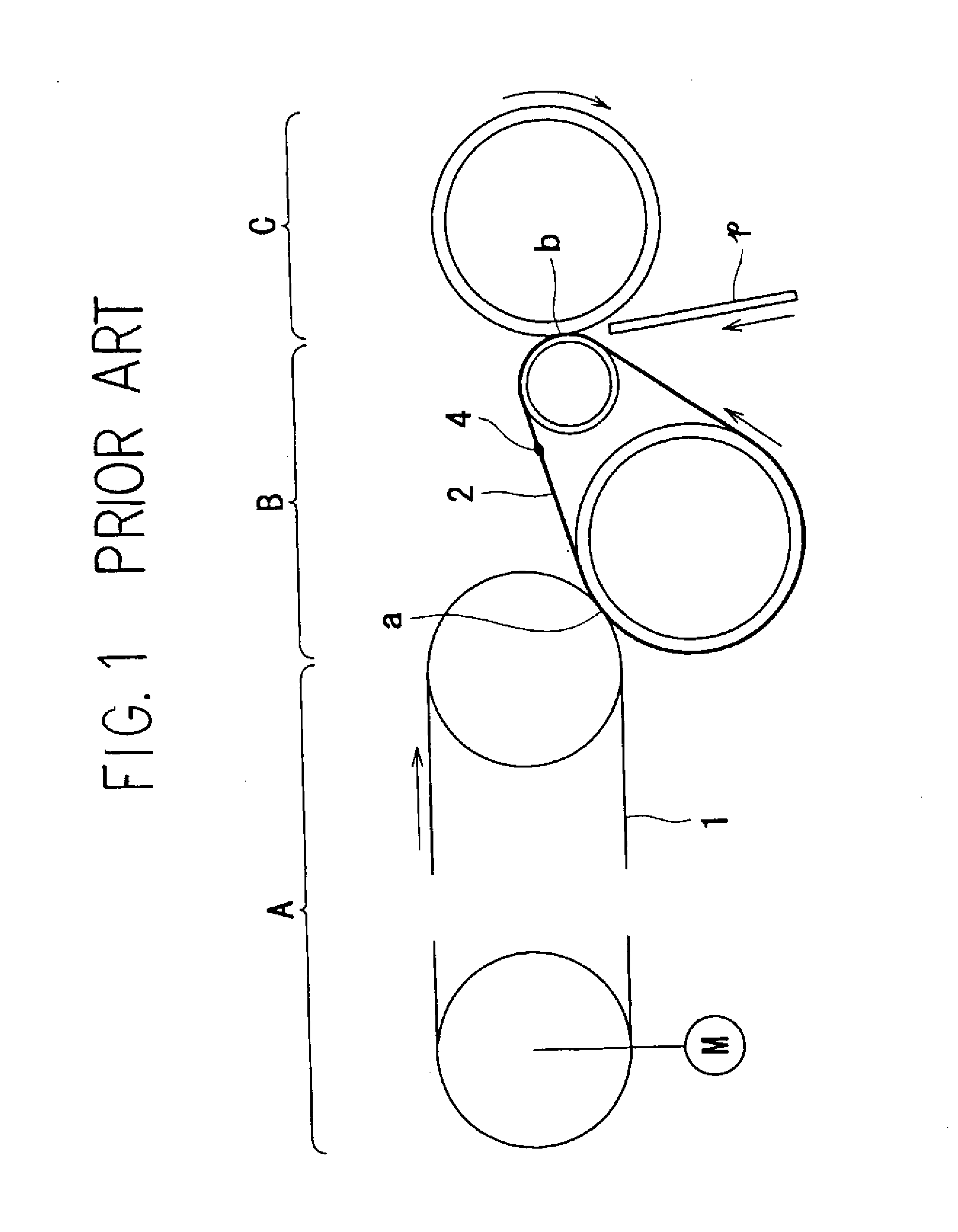
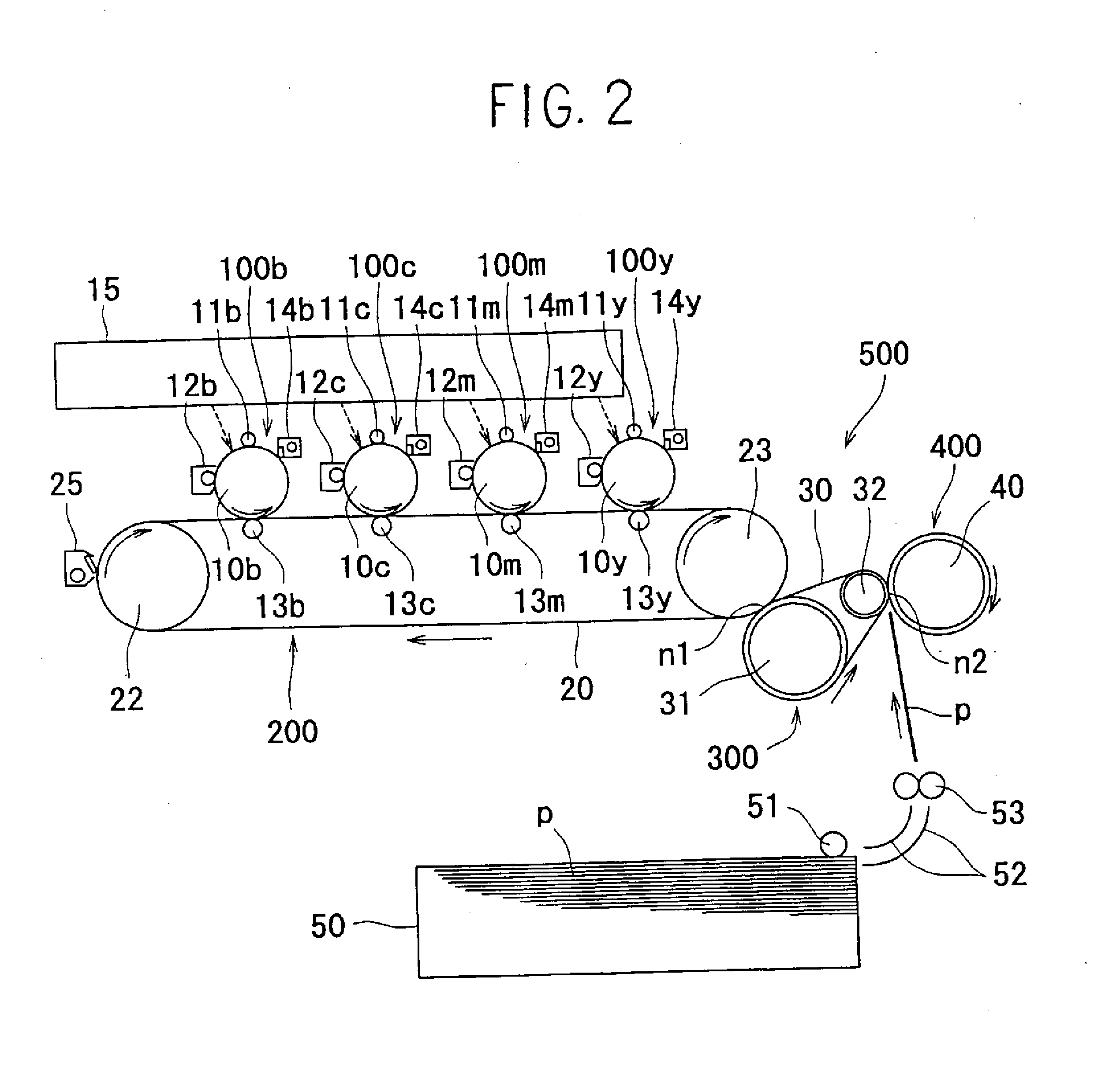
[0069] In modern electrophotographic-type image forming apparatuses an electrostatic latent image is formed on a photoconductive drum or photoconductive belt, the electrostatic latent image is visualized and formed as a toner image by fixing of toner by a developing device, the toner image is primary transferred onto an endless belt-like intermediate transfer member, and the toner image primary transferred onto this intermediate transfer member is secondary transferred onto a recording medium P such as blank paper or an OHP film or the like. For example, as shown in FIG. 1, an image is transferred from a photoconductive belt 1 to a recording medium P by primary transfer of a toner image carried on the photoconductive belt 1 of an image carrier device A onto an endless belt (intermediate transfer member) 2 of an interm...

second embodiment

[0142] The description of this embodiment is based on a description of the prior art pertaining to this embodiment as given hereinafter with reference to the drawings.

[0143]FIG. 13 shows a configuration of a primary transfer portion and secondary transfer portion of a conventional color image forming apparatus. The symbol D in the diagram denotes the primary transfer portion and the symbol E denotes the secondary transfer portion. Furthermore, the symbol 2 denotes an endless belt serving as an intermediate transfer member, 9 denotes a drive roller, 18 denotes a resist roller, 21a denotes a secondary transfer roller, 21b denotes an opposing roller, P denotes a recording material, M denotes a DC motor or pulse motor serving as a drive source, and b denotes a nip portion formed between the secondary transfer roller 21a and opposing roller 21b.

[0144] In a color image forming apparatus such as this, when the recording material P being carried in the direction shown by the arrow in the ...


PUM


Abstract

An image transfer device provided in an image forming apparatus in which, employing an endless belt as an intermediate transfer member, image transfer is performed at nip positions of a primary transfer portion and secondary transfer portion. Generation of warp in the transferred image resulting from transmission of fluctuations in load and torque of the endless belt generated at the nip position of one transfer portion nip to the nip position of the other transfer portion is prevented. The endless belt is turned between rollers and the endless belt is individually driven at the primary transfer portion and secondary transfer portion by drive sources to generate deflection between the primary transfer portion and the secondary transfer portion.

Description

BACKGROUND OF THE INVENTION [0001] 1. Field of the Invention [0002] The present invention relates to an image forming apparatus such as a copier, printer, facsimile device, printing press or composite machines thereof, and more particularly to an image transfer device of a type for forming an electrostatic latent image on an image carrier and performing a primary transfer of a toner image obtained by developing this electrostatic latent image onto an endless belt serving as an intermediate transfer member at a primary transfer portion, that is to say, a primary transfer nip position, and performing a secondary transfer of the toner image that has been primary transferred onto the endless belt onto a recording medium, such as a sheet, carried to a secondary transfer portion, that is to say, a secondary transfer nip position. [0003] 2. Description of the Related Art [0004] While a seamless, endless belt is preferably employed as the intermediate transfer member in the image transfer d...

Claims


Application Information

Patent Timeline
IPC IPC(8): G03G15/16
CPCG03G15/162G03G15/161
Inventor TAKEMOTO, TAKESHISETO, TAKASHIMIYAWAKI, KATSUAKIFUJITA, TAKASHITAKAGAKI, HIROMITSUNAKAFUJI, ATSUHIKAYAHARA, SHINTAMURA, HIROHMISUZUKI, KAZUMI
Owner RICOH KK
Why Eureka
Try Eureka