Centrifugal fan

a centrifugal fan and fan body technology, applied in the direction of positive displacement liquid engine, piston pump, liquid fuel engine, etc., can solve the problem of difficult to reduce the size of the housing

Inactive Publication Date: 2007-09-13
NIDEC CORP
View PDF6 Cites 49 Cited by
  • Summary
  • Abstract
  • Description
  • Claims
  • Application Information

AI Technical Summary

Problems solved by technology

It is therefore difficult to reduce the size of the housing, while ensuring a large passage for an air flow formed between the impeller and the sidewall of the housing and keeping an air flow rate at an adequate level.

Method used


Image

  • Centrifugal fan
  • Centrifugal fan
  • Centrifugal fan

Examples


Embodiment Construction

[0029]Referring to FIGS. 1 through 19, preferred embodiments of the present invention will be described in detail. It should be noted that in the explanation of the present invention, when positional relationships among and orientations of the different components are described as being up / down or left / right, ultimately positional relationships and orientations that are in the drawings are indicated; positional relationships among and orientations of the components once having been assembled into an actual device are not indicated. Meanwhile, in the following description, an axial direction indicates a direction parallel to a rotation axis, and a radial direction indicates a direction perpendicular to the rotation axis.

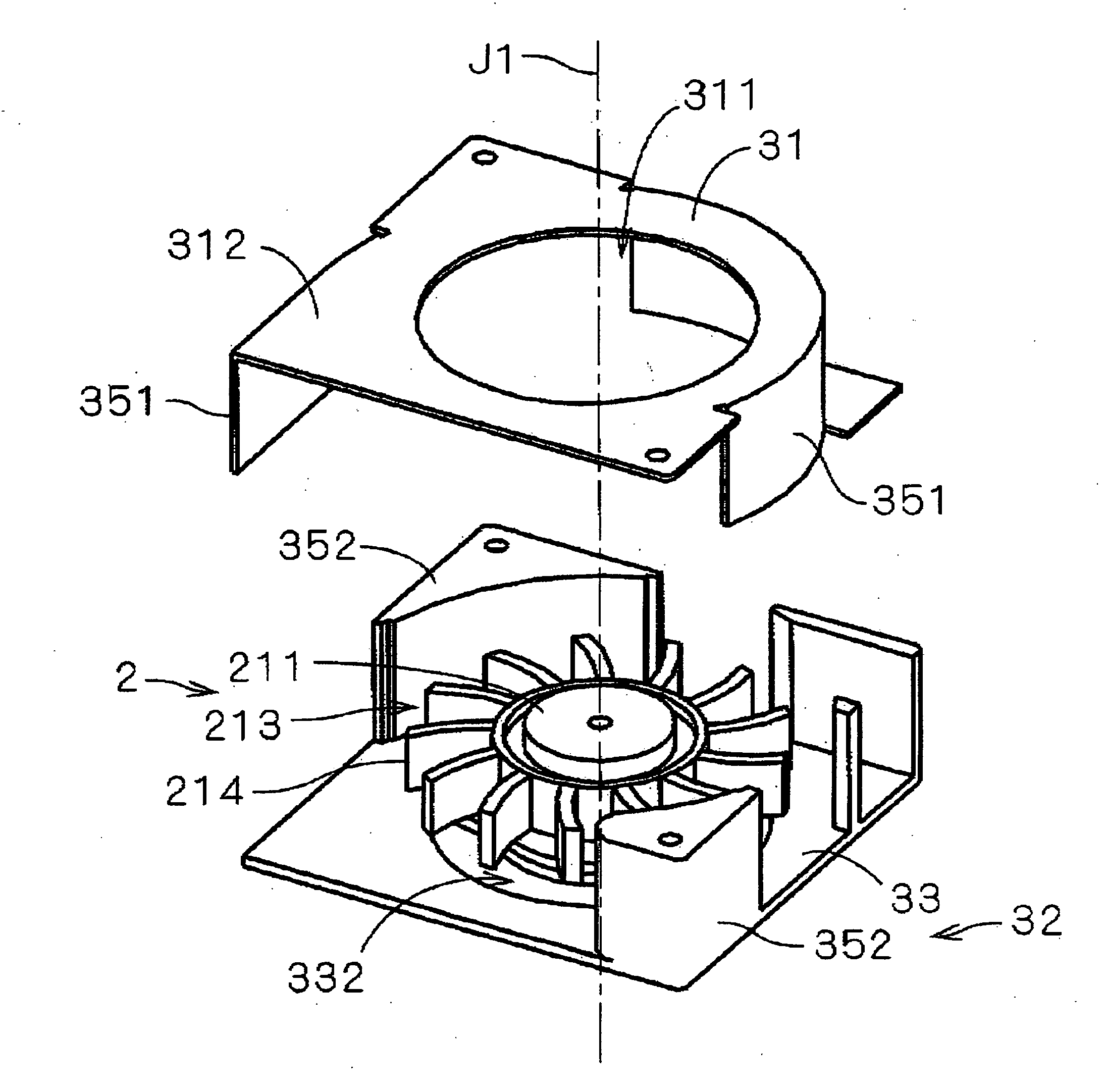
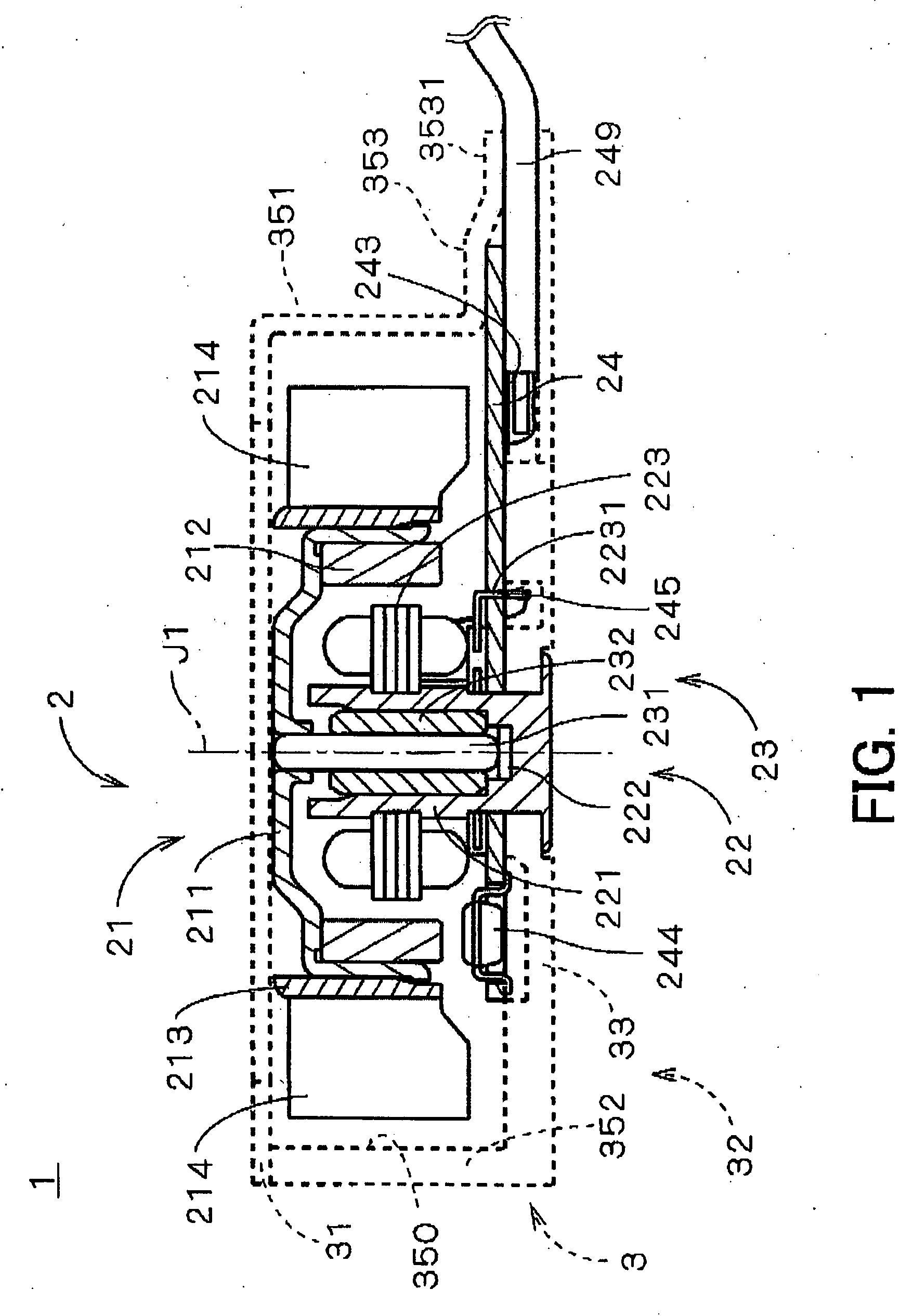
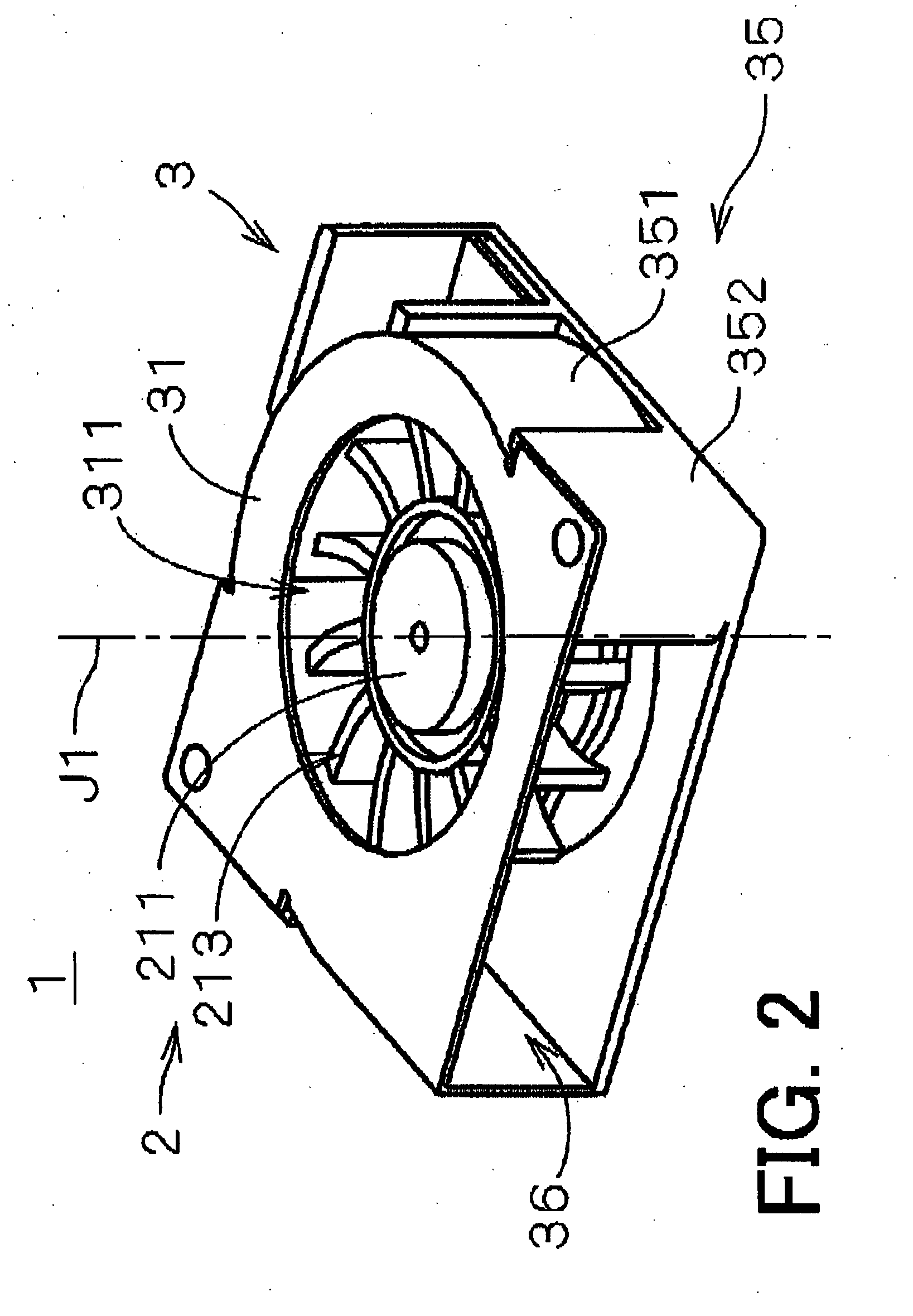
[0030]FIG. 1 is a vertical cross-sectional view of a compact centrifugal fan 1 according to a first preferred embodiment of the present invention. FIG. 2 is a perspective view showing an appearance of the centrifugal fan 1 ofFIG. 1. FIG. 3 is a perspective view of the...


PUM


Abstract

A centrifugal fan includes a motor having an impeller and a housing for accommodating the motor. The housing has a sidewall surrounding an outer circumference of the impeller. An air inlet is formed in the housing and opposed to a center portion of the impeller. An air outlet is formed in the sidewall of the housing and opposed to an outer surface of the impeller. The housing includes a housing body and a housing cover. The housing body has a bottom with the motor secured thereon. The housing cover, formed by a pressed metal member, has an upper part and a cover sidewall extending from the upper part toward the bottom of the housing body and forming at least a part of the sidewall of the housing.

Description

BACKGROUND OF THE INVENTION[0001]1. Field of the Invention[0002]The present invention relates to an electric centrifugal fan used for blowing air.[0003]2. Description of the Related Art[0004]Centrifugal fans are conventionally used for cooling devices in various electronic devices. The centrifugal fans include an impeller having a plurality of blades inside a housing, and draw air in an axial direction parallel to a rotation axis of the impeller and discharge the air in a radial direction perpendicular to the axial direction. The housing usually includes a housing body having a bottom on which a motor is secured and a sidewall which defines a passage of an air flow together with the impeller, and a housing cover closing a top of the housing body. The housing body and the housing cover are formed by resin molding. For the housing cover, the use of material excellent in heat radiation other than the resin, such as aluminum, has been proposed (see Japanese Laid-Open Patent Publication ...

Claims


Application Information

Patent Timeline
Patent Type & Authority Applications(United States)
IPC IPC(8): F04D29/44
CPCF04D25/0613F04D29/626F04D29/441
Inventor TESHIMA, HIROYOSHITAKESHITA, KAZUMIKONISHI, HIDEAKIIDA, KIYOTOTAKAOKA, TSUKASA
Owner NIDEC CORP
Why Eureka
Try Eureka